
User Guide


Crestron CNXRMC Room Solution Box
Operations Guide – DOC. 8162A Room Solution Box: CNXRMC • 9
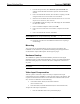
2. Search the DVD for the chapter that displays the multi-burst pattern, as
shown in the following illustration.
3. While the pattern is being displayed on the monitor, use the
screwdriver to adjust the VIDEO INPUT COMP 1 compensation pot
until the line intensity on the monitor appears uniform. Note the
numeric value.
4. Adjust the other two compensation pots (VIDEO INPUT COMP 2
& 3) to the same value as the VIDEO INPUT COMP 1 compensation
pot.
NOTE: For S-video and component video sources, be sure to adjust the pot for
luminance compensation first (VIDEO INPUT COMP 1). The pots for
chrominance compensation should be adjusted last.
Audio/Video Distribution
As previously stated, the CNXRMC receives video and digital audio from the
Crestron CNX-PVID8 via CAT5 cabling. The unit’s circuitry routes these inputs to
local outputs; the individual outputs are enabled under program control.
The following paragraphs describe signal distribution arrangements that are typical
for the CNXRMC.
NOTE: For additional information on video connections over CAT5, refer to the
latest version of the Crestron CAT5 Wiring Reference Guide (Doc. 6137) which is
available from the Downloads | Product Manuals section of the Crestron website
(www.crestron.com).
Audio/Video Signal Routing
Refer to the block diagram on the next page for additional details of the CNXRMC
signal routing capabilities. The input designations (1 – 4) correspond to the output
levels of the CNX-PVID8. Internal signal routing makes it possible for all video
formats to be available without having to rearrange cable connections. Only one
format is allowed at a time; output signals are enabled under program control.