Crestron CP3 3-Series Control System™ Operations Guide
This document was prepared and written by the Technical Documentation department at: Regulatory Compliance As of the date of manufacture, the CP3 has been tested and found to comply with specifications for CE marking and standards per EMC and Radiocommunications Compliance Labelling. Federal Communications Commission (FCC) Compliance Statement This device complies with part 15 of the FCC Rules.
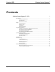
Crestron CP3 3-Series Control System™ Contents 3-Series Control System™: CP3 1 Introduction ............................................................................................................................... 1 Features and Functions ................................................................................................ 1 Specifications .............................................................................................................. 3 Physical Description ...............
Crestron CP3 3-Series Control System™ 3-Series Control System™: CP3 Introduction The Crestron® CP3 presents a new benchmark in control system technology. Featuring the Core 3 OS™ control engine, the CP3 forms the core of any modern networked home or commercial building, managing and integrating all the disparate technologies throughout your facility to make life easier, greener, more productive, and more enjoyable.
Crestron CP3 3-Series Control System™ Features and Functions (Continued) • • • • • • • • Backward compatible to run existing SIMPL programs Full Unicode (multi-language) support Increased network throughput and security Native Active Directory IIS v 6.
Crestron CP3 3-Series Control System™ e-Control Remote Access Years ago, Crestron pioneered the world’s first IP-based control system unleashing vast new possibilities for controlling, monitoring, and managing integrated systems over a LAN, WAN, and the Internet. Today, our many e-Control® solutions offer more ways than ever to control your world the way you want. With e-Control, you can control anything in your home or office from anywhere in the world using a smartphone, tablet, or computer.
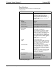
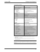
Crestron CP3 3-Series Control System™ Specifications Specifications for the CP3 are listed in the following table.
Crestron CP3 3-Series Control System™ CP3 Specifications (Continued) 1 . SPECIFICATION 3 Default Net ID M e Minimum 3-Series Control 4 m System Update File o Environmental r y Temperature Humidity c a Heat Dissipation r Enclosure d DETAILS 02 Version 1.2.
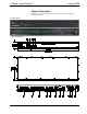
3-Series Control System™ Crestron CP3 Physical Description This section provides information on the connections, controls and indicators available on your CP3. CP3 Physical View CP3 Overall Dimensions 6 • 3 – Series Control System™: CP3 Operations Guide – DOC.
Crestron CP3 3-Series Control System™ Connectors, Controls & Indicators # CONNECTORS*, CONTROLS & INDICATORS 1 COMPUTER 2 PWR LED Green LED, indicates operating power supplied from power pack or Cresnet network 3 NET LED Amber LED, indicates communication with the Cresnet system 4 MSG LED Red LED, indicates control system has generated an error message 5 RESET BUTTONS 6 RELAY OUTPUT (1 – 8) (2) 8-pin 3.
Crestron CP3 3-Series Control System™ Connectors, Controls & Indicators (Continued) # CONNECTORS*, CONTROLS & INDICATORS 9 COM1 DESCRIPTION (1) 5-pin 3.5 mm detachable terminal block Bidirectional RS-232/422/485 port Up to 115.2k baud; hardware and software handshaking support PIN # 1 2 3 4 5 10 COM (2 – 3) RS-232 GND TX RX RTS CTS RS-422/485 GND TXRX+ TX+ RX- (2) 3-pin 3.5 mm detachable terminal blocks Bidirectional RS-232 ports Up to 115.
Crestron CP3 3-Series Control System™ Connectors, Controls & Indicators (Continued) * Operations Guide – DOC. 7316A # CONNECTORS*, CONTROLS & INDICATORS DESCRIPTION 15 POWER (1) 2.1 mm barrel DC power jack, 24 Volt DC power input Power supply included Passes through to NET port to power Cresnet devices 16 G (1) 6 – 32 screw, chassis ground lug Interface connectors for RELAY OUTPUT, I/O, IR-SERIAL OUTPUT, COM1, COM 2 -3, and NET ports are provided with the unit.
Crestron CP3 3-Series Control System™ Setup Network Wiring When wiring the Cresnet or Ethernet network, consider the following: • Use Crestron Certified Wire. • Use Crestron power supplies for Crestron equipment. • Provide sufficient power to the system. CAUTION: Insufficient power can lead to unpredictable results or damage to the equipment. Use the Crestron Power Calculator to help calculate how much power is needed for the system (www.crestron.com/calculators).
Crestron CP3 3-Series Control System™ Installation Ventilation The CP3 should be used in a well-ventilated area. The venting holes should not be obstructed under any circumstances. To prevent overheating, do not operate this product in an area that exceeds the environmental temperature range listed in the table of specifications. Consider using forced air ventilation and/or incrementing the spacing between units to reduce overheating.
Crestron CP3 3-Series Control System™ Ear Attachment for Rack Mounting 4. Bussing Strip Installation Repeat procedure (steps 1 through 3) to attach the remaining ears to the opposite side. The CP3 is supplied with a brass bussing strip to facilitate commoning (linking) of multiple terminal block connections. The bussing strip is constructed with four terminal block positions and may be trimmed to size for various applications or different devices.
Crestron CP3 Stacking 3-Series Control System™ Four “feet” are provided with the CP3 so that if the unit is not rack mounted, the rubber feet can provide stability when the unit is placed on a flat surface or stacked. These feet should be attached prior to the hookup procedure. Refer to the following illustration for placement of the feet. Foot Placement for the CP3 NOTE: No more than two CP3 units should be stacked.
3-Series Control System™ Crestron CP3 Hardware Connections for the CP3 NOTE: Ensure the unit is properly grounded by connecting the chassis ground lug to an earth ground (building steel). NOTE: To prevent overheating, do not operate this product in an area that exceeds the environmental temperature range listed in the table of specifications. NOTE: The CP3 can be powered by the 4-position terminal block connector labeled NET with the (included) 24V DC power).
Crestron CP3 3-Series Control System™ Programming Software Have a question or comment about Crestron software? Answers to frequently asked questions (FAQs) can be viewed in the Online Help section of the Crestron Web site. To post a question or view questions you have submitted to Crestron’s True Blue Support, log in at www.crestron.com/support. First-time users must establish a user account.
Crestron CP3 3-Series Control System™ Programming with SIMPL Windows NOTE: While SIMPL Windows can be used to program the CP3, it is recommended to use SystemBuilder for configuring a system. SIMPL Windows is Crestron’s premier software for programming Crestron control systems. It is organized into two separate but equally important “Managers”: Configuration and Program.
Crestron CP3 3-Series Control System™ Uploading and Upgrading Crestron recommends using the latest programming software and that each device contains the latest firmware to take advantage of the most recently released features. However, before attempting to upload or upgrade it is necessary to establish communication. Once communication has been established, files (for example, programs or firmware) can be transferred to the control system (and/or device).
3-Series Control System™ USB Crestron CP3 NOTE: Required for initial setup of Ethernet parameters. NOTE: Required for loading projects and firmware. USB Communication PC Running Crestron Toolbox CP3 USB The COMPUTER port on the CP3 connects to the USB port on the PC via the included Type A to Type B USB cable: TCP/IP 1. Use the Address Book in Crestron Toolbox to create an entry using the expected communication protocol (USB).
Crestron CP3 3-Series Control System™ 8. Add, modify or delete entries in the IP table. The CP3 can have only one IP table entry. 9. A defined IP table can be saved to a file or sent to the device. 10. When using the CP3 as a “slave”, edit the “master” control system’s IP table to include an entry for the CP3. The entry should list the CP3’s IP ID (specified on the CP3’s IP table) and its IP address.
3-Series Control System™ Crestron CP3 Operation Crestron 3-Series Control Systems are the brain of a complete integrated audio/visual or automation solution, serving as the central processor and I/O interface. Every audio, video and environmental element of the home, boardroom, classroom or command center becomes integrated and accessible through the control system. No matter how complex or basic, Crestron control systems are entirely custom-programmable to attain the exact functionality required.
Crestron CP3 3-Series Control System™ Problem Solving Troubleshooting The following table provides corrective action for possible trouble situations. If further assistance is required, please contact a Crestron customer service representative. CP3 Troubleshooting TROUBLE POSSIBLE CAUSE(S) CORRECTIVE ACTION Device is not communicating with the network. Use Crestron Toolbox to poll the network. Verify network connection to the device. Device is not receiving power from a Crestron power source.
Crestron CP3 3-Series Control System™ CP3 Troubleshooting (Continued) TROUBLE POSSIBLE CAUSE(S) A/V system device does not respond. CORRECTIVE ACTION IRP2 or serial port not placed properly. Verify placement of IRP2 (hold phosphor card under IRP2 while pressing button) and tighten serial cables. Used wrong IR/serial port. Verify that proper IR or serial port is defined. Serial cable not wired correctly. Verify that serial cable is wired correctly for RS-232, 422, 485.
Crestron CP3 3-Series Control System™ Cresnet power usage of that unit is the Cresnet power usage of the entire run. The wire gauge and the Cresnet power usage of the run should be used in the following equation to calculate the cable length value on the equation’s left side. Cable Length Equation L< 40,000 RxP Where: L = Length of run (or chain) in feet R = 6 Ohms (Crestron Certified Wire: 18 AWG (0.75 mm 2 )) or 1.
3-Series Control System™ Crestron CP3 Future Updates As Crestron improves functions, adds new features and extends the capabilities of the CP3, additional information may be made available as manual updates. These updates are solely electronic and serve as intermediary supplements prior to the release of a complete technical documentation revision. Check the Crestron Web site periodically for manual update availability and its relevance. Updates are identified as an “Addendum” in the Download column.
Crestron CP3 3-Series Control System™ Return and Warranty Policies Merchandise Returns / Repair Service 1. No merchandise may be returned for credit, exchange or service without prior authorization from Crestron. To obtain warranty service for Crestron products, contact an authorized Crestron dealer. Only authorized Crestron dealers may contact the factory and request an RMA (Return Merchandise Authorization) number.
Crestron CP3 3-Series Control System™ This page is intentionally left blank. 26 • 3 – Series Control System™: CP3 Operations Guide – DOC.
Crestron CP3 3-Series Control System™ This page is intentionally left blank. Operations Guide – DOC.
Crestron Electronics, Inc. 15 Volvo Drive Rockleigh, NJ 07647 Tel: 888.CRESTRON Fax: 201.767.7576 www.crestron.com Operations Guide – DOC. 7316A (2032696) 02.12 Specifications subject to change without notice.