
Specifications
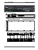


3-Series Control Systems Crestron CP3& CP3N
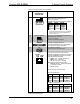
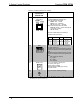
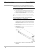
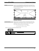
Connectors, Controls & Indicators
# CONNECTORS*,
CONTROLS &
INDICATORS
DESCRIPTION
1 COMPUTER
(1) USB Type B female, USB 2.0 computer
console port (cable included); For setup only
PIN DESCRIPTION
1 +5 VDC
2 Data -
3 Data +
4 Ground
2 PWR LED
(1) Green LED, indicates operating power
supplied from power pack or Cresnet network
3 NET LED
(1) Amber LED, indicates communication with
the Cresnet system
4 MSG LED
(1) Red LED, indicates control system has
generated an error message
5 RESET BUTTONS
HW-R – (1) Recessed push button for
hardware reset
SW-R –(1) Recessed push button for software
reset
6
RELAY OUTPUT (1 – 8)
(2) 8-pin 3.5 mm detachable terminal blocks
comprising (8) normally open, isolated
relays; Rated 1 amp, 30 volts ac/dc;
MOV arc suppression across contacts
7
I/O (1-8)
(1) 9-pin 3.5 mm detachable terminal block
comprising (8) “Versiport” digital input/output
or analog input ports (referenced to GND);
Digital Input: Rated for 0-24 volts dc, input
impedance 20k Ω, logic threshold >3.125 V
low/0 and <1.875 V high/1;
Digital Output: 250 mA sink from maximum
24 volts dc, catch diodes for use with “real
world” loads;
Analog Input: Rated for 0-10 volts dc,
protected to 24 volts dc maximum, input
impedance 21k Ω with pull-up resistor
disabled;
Programmable 5 volts, 2k Ω pull-up resistor
per pin
8
IR – SERIAL OUTPUT
(1-8)
8 3-Series Control Systems: CP3 & CP3N Operations Guide – DOC. 7316B
(2) 8-pin 3.5 mm detachable terminal blocks
comprising (8) IR/Serial output ports;
IR output up to 1.2 MHz;
1-way serial TTL/RS-232 (0-5 volts) up to
115.2k baud
(Continued on following page)