
Specifications


3-Series Control Systems Crestron CP3& CP3N
Connectors, Controls & Indicators (Continued)
#
CONNECTORS*,
CONTROLS &
INDICATORS
DESCRIPTION
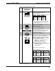
14
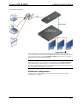
CONTROL SUBNET
(CP3N Only)
(1) 8-pin RJ-45 with two LED indicators;
10/100/1000BASE-T Ethernet port;
Left LED indicates link status;
Amber: Link – 1 Gbps
Green: Link – 100 Mbps
Off: No link or Link – 10 Mbps
Right LED indicates Ethernet activity
Flashing: Activity – Flash rate depends
on amount of activity
Off: No Activity
Provides a dedicated local network for
Crestron Ethernet devices
PIN SIGNAL PIN SIGNAL
1 BI_DA + 5 BI_DC -
2 BI_DA- - 6 BI_DB -
3 BI_DB + 7 BI_DD +
4 BI_DC + 8 BI_DD -
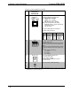
15
NET
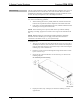
(1) 4-pin 3.5 mm detachable terminal block,
Cresnet master port;
Outputs power to Cresnet devices if a power
pack is connected to the 24 Vdc power input
jack;
Receives Cresnet network power if no power
pack is connected to the 24 Vdc power input
jack
24: Power (24 volts dc)
Y: Data
Z: Data
G: Ground
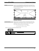
16 24VDC 2.0A
(1) 2.1 mm barrel dc power jack,
24 volt dc power input
Power supply included;
Passes through to NET port to power
Cresnet devices
17 G
(1) 6–32 screw, chassis ground lug
* Interface connectors for RELAY OUTPUT, I/O, IR-SERIAL OUTPUT, COM1, COM 2, COM 3,
and NET ports are provided with the unit.
10 3-Series Control Systems: CP3 & CP3N Operations Guide – DOC. 7316B