
Specifications
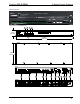


3-Series Control Systems Crestron CP3& CP3N
12 3-Series Control Systems: CP3 & CP3N Operations Guide – DOC. 7316B
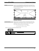
Rack Mounting
The CP3 can be mounted in a rack or stacked with other equipment. Two “ears” are
provided with the CP3 so that the unit can be rack mounted. These ears must be
installed prior to mounting. Complete the following procedure to attach the ears to
the unit. The only tool required is a #1 or #2 Phillips screwdriver.
WARNING: To prevent bodily injury when mounting or servicing this unit in a
rack, observe the following guidelines:
When mounting this unit in a partially filled rack, load the rack from the
bottom to the top with the heaviest component at the bottom of the rack.
If the rack is provided with stabilizing devices, install the stabilizers before
mounting or servicing the unit in the rack.
NOTE: If rack mounting is not required, rubber feet are provided for tabletop
mounting or stacking. Apply the feet near the corner edges on the underside of the
unit.
NOTE: Reliable earthing of rack-mounted equipment should be maintained.
Particular attention should be given to supply connections other than direct
connections to the branch circuit (e.g. use of power strips).
To install the ears:
1. There are screws that secure each side of the CP3 top cover. Using a #1 or
#2 Phillips screwdriver, remove the three screws closest to the front panel
from one side of the unit. Set screws aside for step 3. Refer to the diagram
following step 3 for a detailed view.
2. Position a rack ear so that its mounting holes align with the holes vacated
by the screws in step 1.
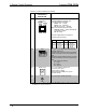
3. Secure the ear to the unit with three screws from step 1, as shown in the
following diagram.
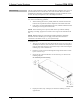
Ear Attachment for Rack Mounting
4. Repeat procedure (steps 1 through 3) to attach the remaining ear to the
opposite side.