
Specifications


Crestron CP3 & CP3N 3-Series Control Systems
Operations Guide – DOC. 7316B 3-Series Control Systems: CP3 & CP3N 13
Stacking
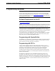
Four “feet” are provided with the CP3 so that if the unit is not rack mounted, the
rubber feet can provide stability when the unit is placed on a flat surface or stacked.
These feet should be attached prior to the hookup procedure. Refer to the following
illustration for placement of the feet.
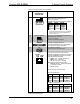
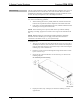
Foot Placement for the CP3
Mounting Feet (2002389), Qty. 4
NOTE: No more than two CP3 units should be stacked.
Hardware Hookup
Connect the Device
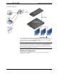
Make the necessary connections as called out in the illustration that follows this
paragraph. Refer to “Network Wiring” on page 11 before attaching the 4-position
termin
al block connector. Apply power after all connections have been made.
When making connections to the CP3, note the following:
Use Crestron power supplies for Crestron equipment.
The included cable(s) cannot be extended.
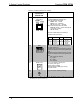
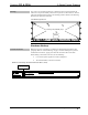
Hardware Connection for the CP3and CP3N (CP3 Shown, Front)
COMPUTER:
To Computer Console