
Specifications
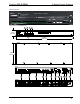


3-Series Control Systems Crestron CP3& CP3N
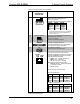
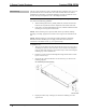
Hardware Connections for the CP3 (Rear)
COM 1:
To Serial
Controlled
Devices
COM 2 & 3:
To Serial
Controlled
Devices
RELAY OUTPUT (1-8):
To Contact Closure
Devices
IR-SERIAL (1-8):
To TTL/RS-232 Devices
MEMO RY:
MMC Compatible
Card Slot
LAN:
10BASE-T/100BASE-TX
Ethernet to LAN
USB:
To Storage Devices
NET:
To Cresnet Devices
24V DC, 2.0 A:
From AC Power
Pack
Ground
I/O (1-8):
To Controllable Devices
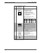
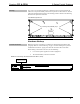
Hardware Connections for the CP3N (Rear)
RELAY OUTPUT (1-8):
To Contact Closure
Devices
IR-SERIAL (1-8):
To TTL/RS-232 Devices
COM 1:
To Serial
Controlled
Devices
COM 2 & 3:
To Serial
Controlled
Devices
MEMO RY:
MMC Compatible
Card Slot
LAN:
10/100/1000BASE-T
Ethernet to LAN
24V DC, 2.0 A:
From AC Power
Pack
Ground
USB:
To Storage Devices
NET:
To Cresnet Devices
I/O (1-8):
To Controllable Devices
CONTROL SUBNET:
10/100/1000BASE-T
Ethernet to Control Subnet
NOTE: Ensure the unit is properly grounded by connecting the chassis ground lug
to an earth ground (building steel).
NOTE: To prevent overheating, do not operate this product in an area that exceeds
the environmental temperature range listed in the table of specifications.
NOTE: The CP3 can be powered by the 4-position terminal block connector labeled
NET or with the (included) 24 Vdc power pack.
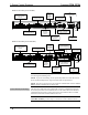
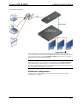
Control Subnet (CP3N Only)
The CP3N has a dedicated Control Subnet that is used for communication between
the control system and Crestron Ethernet devices. This subnet allows for dedicated
communication between the control system and Crestron Ethernet devices without
interferences from other network traffic on the LAN.
CAUTION: Do not connect the CONTROL SUBNET port to the LAN. The
CONTROL SUBNET port must only be connected to Crestron Ethernet devices.
14 3-Series Control Systems: CP3 & CP3N Operations Guide – DOC. 7316B