Crestron CPC-CAMI Pan/Tilt Camera Head with Control Interface Contents Pan/Tilt Camera Head with Control Interface: CPC-CAMI 1 Description................................................................................................................................. 1 Functional Description ................................................................................................ 1 Physical Description................................................................................................
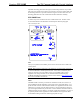
Crestron CPC-CAMI Pan/Tilt Camera Head with Control Interface Pan/Tilt Camera Head with Control Interface: CPC-CAMI Description Functional Description The CPC-CAMI is an integrated pan/tilt head and network control interface belonging to the Crestron ProCam family of network camera control. The unit has been designed to provide control of a remotely positioned video camera site. Control is defined as the two-axis motion of the pan/tilt unit and the focus/zoom setting of a camera lens.
Pan/Tilt Camera Head with Control Interface Crestron CPC-CAMI Presets In conjunction with the Crestron control system, the CPC-CAMI is capable of “memorizing” pan/tilt positions and focus/zoom settings for a virtually unlimited number of presets. Each preset stores a specific position and setting. Positional feedback signals are essential to the implementation of presets; unless the lens supports position mode.
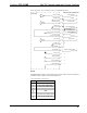
Crestron CPC-CAMI Pan/Tilt Camera Head with Control Interface Adjustable mounting plates (flat and angled) and mounting hardware are provided with each CPC-CAMI. The two plates can be fixed to one of the rotating disks with the mounting hardware to provide camera/lens support. The other disk serves as a mounting platform for the CPC-CAMI with attached camera/lens assembly. CPC-CAMI Ports A number of ports are located on the CPC-CAMI interface box. Each has a silkscreened label.
Pan/Tilt Camera Head with Control Interface Crestron CPC-CAMI CPC-CAMI Pinout for LENS Port PIN DESCRIPTION 1 2 3 4 5 6 7 8 9 10 11 12 13 14 15 Focus Out Focus Common Zoom Out Zoom Common Rate/Position Mode 5V Reference from Lens 7.
Crestron CPC-CAMI Pan/Tilt Camera Head with Control Interface Wiring Diagram for Lens C (KTS/KTS-A Series and MD/BMD/SD Series) HIROSE LENSE CONNECTOR CPC-CAMI FOCUS_MOTOR POWER_GND ZOOM_MOTOR POWER_GND FOCUS CONTROL 1 GROUND 2 ZOOM CONTROL 3 FOCUS SPEED/POS SIG 5 IRIS SPEED/POS SIG +5V_VOLTS_LENSE_REFERENCE 7_VOLTS_FROM_LENSE IRIS_MOTOR POWER_GND IRIS_CONTROL_1 IRIS_CONTROL_2 ANALOG_+5V ZOOM_FEEDBACK FOCUS_FEEDBACK ANALOG_GROUND 3 9 4 ZOOM SPEED/POS SIG RATE/POSITION 8 SIGNAL C
Pan/Tilt Camera Head with Control Interface Crestron CPC-CAMI CPC-CAMI Indicators A number of indicators are located on the CPC-CAMI interface box. Each has a silkscreened label. Refer to the illustration shown in “CPC-CAMI Ports” on page 3 and the descriptions after this paragraph. POWER This LED illuminates when 24 VDC is supplied to the CPC-CAMI. NET This LED illuminates when communication between the control system and the CPC-CAMI is established.
Crestron CPC-CAMI Pan/Tilt Camera Head with Control Interface Leading Specifications The table below provides a summary of leading specifications for the CPC-CAMI. Dimensions and weights are rounded to the nearest hundredth unit. Leading Specifications of the CPC-CAMI SPECIFICATION DETAILS Power Requirements 24 VDC, 2.5A; 60 Watts Default Network ID 34 SIMPL™ Windows® Version 1.18 or later CNMSX-AV/PRO Upgrade File (.upz) Version 5.01.35x or later CNRACKX/-DP Upgrade File (.upz) Version 5.07.
Pan/Tilt Camera Head with Control Interface Crestron CPC-CAMI Leading Operational Specifications of the CPC-CAMI SPECIFICATION DETAILS Operating Speeds Pan (horizontal) 22.5 degrees/second Maximum Camera/ Lens Load 15 lbs. (6.80 kg) - (balanced) Preset Recall Resolution +/- 0.25 degrees Tilt (vertical) 20.0 degrees/second As of the date of manufacture, the unit has been tested and found to comply with specifications for CE marking. NOTE: These devices comply with part 15 of the FCC rules.
Crestron CPC-CAMI Pan/Tilt Camera Head with Control Interface Determining Camera/Lens Assembly Center of Gravity LENS CAMERA FLAT MOUNTING PLATE 1/4-20 MOUNTING SCREW ROUND OBJECT 5. Use two 1/4-20 x 3/8” pan Phillips head screws (supplied) to loosely secure the angled mounting plate to the CPC-CAMI. Verify that the two pins on the plate align with the slot on the rotating disk. 6. Adjust the vertical position of the angled mounting plate (refer to the illustration below).
Pan/Tilt Camera Head with Control Interface Crestron CPC-CAMI 10. Mount the CPC-CAMI with attached camera/lens assembly to the desired location. Unit mounts on its 3.750 inch (9.525 cm) diameter base with two ¼-20x3/8” pan Philips head screws, 2.000 inches (5.080 cm) on center (refer to the illustration below). NOTE: If longer screws (than the ones supplied) are required to mount the CPCCAMI with attached camera/lens assembly, only allow five turns into the unit’s thread insert.
Crestron CPC-CAMI Pan/Tilt Camera Head with Control Interface 8. To verify this procedure, select Diagnostics | Report Network Devices. Confirm that the CPC-CAMI has a new NET ID code. 9. Reconnect other network or modular devices that were disconnected in step 1. Preparation for Use Refer to the hookup diagram below. Other than connecting the correct jumper board first and making the power connection last, complete the connections in any order.
Pan/Tilt Camera Head with Control Interface Crestron CPC-CAMI Limit Stop Adjustment Two locking screws are found on each rotating disk on the CPC-CAMI. Complete the following steps to properly set the limit stops. 1. Loosen both pan (horizontal drive) and tilt (vertical drive) locking screws. 2. Slowly rotate the camera/lens assembly to the desired left-pan limit. 3. Slide a loosened locking screw until it engages the pan sensor; tighten the locking screw. 4.
Crestron CPC-CAMI Pan/Tilt Camera Head with Control Interface Maintenance NOTE: Do not attempt to open the unit to make any adjustments or repairs. In the event that an operating problem occurs, contact a member of Crestron’s technical support team. Refer to “Further Inquiries” on page 17. The CPC-CAMI has been designed to eliminate the need for periodic maintenance. Lubrication for all moving parts is permanent.
Pan/Tilt Camera Head with Control Interface Crestron CPC-CAMI NOTE: There is no need to recreate this sample SIMPL Windows program. The program is available from the Crestron ControlCD (version 6.2 and later) or the Downloads page (EXAMPLES Library) of the Crestron website (www.crestron.com). Search for CPC-CAMI.SMW. Jumper Board A, B, or D For most "standard" lenses using CPC-CAMI jumper board A, B or D, programming is essentially the same. A sample SIMPL program is shown in block diagram form below.
Crestron CPC-CAMI Pan/Tilt Camera Head with Control Interface Jumper Board C Servo drive lenses requiring jumper board C (such as the Canon KTS and Fujinon MD, BMD series), do not have true feedback pots. Instead they have separate rate and position control modes. If presets are not required, the CNCAMI RATE CONTROL module can be used for direct drive of the rate lines on the CPC-CAMI definition.
Pan/Tilt Camera Head with Control Interface Crestron CPC-CAMI Positional Feedback Signals Positional feedback signals are generated by the networked CPC-CAMI and input to the rest of the program. Four analog positional feedback signals, TILT_POS, PAN_POS, FOC_POS, and ZOOM_POS, represent the current pan/tilt axis position and focus/zoom lens setting. The CPC-CAMI converts positional potentiometer wiper voltages to analog positional feedback signals.
Crestron CPC-CAMI Pan/Tilt Camera Head with Control Interface Problem Solving Troubleshooting The table that follows this paragraph provides corrective action for possible trouble situations. If further assistance is required, please contact a Crestron technical support representative; refer to “Further Inquiries” on page 17. CPC-CAMI Troubleshooting TROUBLE POSSIBLE CAUSE(S) CPC-CAMI does not CPC-CAMI is not receiving function. POWER LED network power. is not illuminated. CPC-CAMI does not function.
Pan/Tilt Camera Head with Control Interface Crestron CPC-CAMI Return and Warranty Policies Merchandise Returns / Repair Service 1. No merchandise may be returned for credit, exchange, or service without prior authorization from CRESTRON. To obtain warranty service for CRESTRON products, contact the factory and request an RMA (Return Merchandise Authorization) number. Enclose a note specifying the nature of the problem, name and phone number of contact person, RMA number, and return address. 2.
Crestron CPC-CAMI Pan/Tilt Camera Head with Control Interface Appendix: Application Examples The application examples in this appendix suggest the lens cabling connection for the lens type jumper (A through D) to be used for a given camera lens. The camera lens pins are listed in the left-most column. The CPC-CAMI LENS connector pins are listed in the right-most column.
Pan/Tilt Camera Head with Control Interface Crestron CPC-CAMI Lens Cabling Connection for Jumper B (+/-8V) Computar H10Z0812M red,blk Lens Common green purple blue orange Focus Motor Drive Feedback Supply Focus Feedback Feedback Ground yellow grey Zoom Motor Drive Zoom Feedback 2 FOCUS 1 12 14 15 ZOOM 3 13 Lens Cabling Connection for Jumper D (+/-6V) CONNECTOR 8000-9801-00 4 Lens Common 3 6 8 5 Focus Motor Drive Feedback Supply Focus Feedback Feedback Ground 2 7 9 Zoom Motor Drive Zoom Feedbac