
User Guide


2 •• Lens Mount Accessory: CPC-LMT Operations & Installation Guide - DOC. 5758
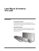
Installation
The CPC-LMT is delivered assembled. Depending on the camera and lens that is
going to be used, the CPC-LMT requires adjustment. The parts bag shipped with the
unit includes tools for adjustments and a spacer for camera mounting. A Phillips tip
screwdriver and hex keys (supplied) are all the hand tools necessary to mount the
CPC-LMT.
Parts Bag Contents
QTY.
ITEM
1 Hex Key (9/64)
1 Hex Key (.050)
1 Hex Key (5/32)
1 Screw 1/4-20x3/4
1 Spacer
NOTE: Before beginning this installation, remove the mounting plates from the
CPC-CAMI and retain the two ¼-20 x 3/8 mounting screws. The CPC-LMT is
installed using these two ¼-20 x 3/8 mounting screws.
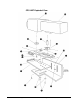
Important:
Call-out numbers refer
to the "CPC-LMT Exploded
View" on page 4,
unless noted otherwise.
1. Assemble the camera and lens to be mounted. Align the camera and lens
mounting holes. Note the distance between the camera and lens mounting
screws and make sure that they fit into the Adjustment Slots of the Camera
Plate (5). There should be excess room to allow for forward/backward
adjustment.
2. Determine the center balance point of the camera/lens assembly. This can be
achieved by placing the camera/lens on a flat surface and inserting a pencil or similar
object beneath the assembly to determine the balance point. Note the balance point.
It should be located at the center of rotation on the CPC-CAMI. The center of
rotation is indicated by Pins (16) on the Platform Support Bracket (1).
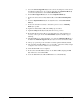
3. In most cases the Lens (14) is physically larger than the Camera (15). If so, discard
Spacer (12). If the Camera (15) is larger than the Lens (14), Spacer (12) should be
used as shown below.
Proper Use of Spacer
NOTE: If Spacer (12) is used, the ¾ inch long Screw (11A) must be used.
4. Remove Camera Support Rod (9) from the CPC-LMT assembly by loosening
Locking Screw (13).