
User Guide


Operations & Installation Guide - DOC. 5758 Lens Mount Accessory: CPC-LMT •• 3
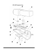
5. Screw the Camera Support Rod (9) into the camera's mounting hole. If the camera
has multiple mounting holes, choose the hole that allows the Adjustment Block (8)
to fit into the adjustment slot in the Camera Mount Plate (5).
6. Insert Camera Support Rod (9) into the in the Adjustment Block (8).
7. Position the camera /lens assembly (14) and (15) on the Camera Mounting Plate
(5).
8. Insert the Adjustment Block (8) into the adjustment slot of the Camera Mount
Plate (5).
9. Position the camera/lens assembly so the balance point is as close to Mounting
Block (6) as possible.
10. Tighten lens Screw (11) or (11A) with a Phillips tip screwdriver.
11. Tighten Locking Screws (10) and (13) with the hex keys provided.
12. Hex Screws (4) and washers (17) provide additional front to back adjustment. If
necessary, select a pair of holes in the Interim Plate (3) that would allow proper
balancing.
13. The CPC-LMT has two width adjustments. Use either the Adjustment Block (6) or
the slots in the Platform Support Arm (1) to adjust for various camera/lens widths.
14. After proper positioning of the camera/lens assembly, tighten Screws (4) and (17).
15. The camera/lens and CPC-LMT are now one assembly. Adjust the assembly's height
to align the center of the lens with the center of tilt rotation.
16. Check all CPC-LMT screws for tightness.
17. Fit the camera and CPC-LMT assembly onto the CPC-CAMI by aligning the Pins
(16) with the slots of the CPC-CAMI.
18. Secure the CPC-LMT to the CPC-CAMI with the two ¼-20 Screws (2).