
Specifications


Electrical Control Interface with AC Crestron CNECI-4A
NOTE: Review the Network Interconnection Diagram (latest revision of Doc.
5411) when making 4-wire connections.
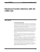
Refer to the diagram below and complete the steps on the next page to hookup the
CNECI-4A:
CNECI-4A Hookup Diagram
1
LOCAL
INPUTS
6
POWER
1
24
Y
Z
G
NET
2
3
4
5
NET
7
8
G
L
H
CODE
ID
G
N
L
L
NC
COM
1234
COM
NO
COM
NC
COM
NO
2
NC
COM
NO
COM
3
NC
COM
COM
NO
4
MODEL: CNECI-4A
CRESTRON
TO
CRESNET
SYSTEM
TO AC
POWERED
DEVICES
FROM
110-125VAC or
220-250VAC
FROM
LOCAL
INPUTS
230
115
6 • Electrical Control Interface with AC: CNECI-4A Operations Guide - DOC. 8149