
Specifications
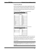
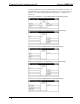

Crestron CNECI-4A Electrical Control Interface with AC
1. Make sure that the Cresnet system and AC power circuits to be
installed are turned off.
2. Remove the four CNECI-4A enclosure front cover screws.
3. Remove the six PCB mounting screws (do not remove the low voltage
section dust cover) and remove the PCB.
4. Mount the CNECI-4A to the desired wall location.
5. Re-install the PCB with the six mounting screws.
6. Remove appropriate conduit knock-out(s) from the side(s) of the
CNECI-4A enclosure.
7. Route the NET and LOCAL INPUTS wiring through the enclosure
knock-out(s).
8. Attach the NET and LOCAL INPUTS wiring to the 4-position and
9-position terminal blocks, respectively, but do not connect the terminal
blocks to the CNECI-4A.
9. Route the AC powered device wiring and AC power wiring through the
enclosure knock-out(s) but do not connect.
CAUTION: To prevent damage to the unit, do not connect the NET terminal block
and AC power wiring until the other wiring has been connected or attached.
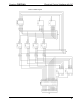
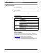
10. Connect the terminal blocks and wiring as shown in the hookup
diagram.
11. Make sure that the AC voltage selector switch is positioned for the
appropriate (115 for 110-125VAC or 230 for 220-250VAC) voltage.
12. Apply Cresnet system and/or AC power to the CNECI-4A.
13. Confirm that the POWER and NET indicators illuminate. (The relay
LEDs illuminate when the corresponding relay energizes.)
14. Re-install the enclosure front cover with the four cover screws.
Identity Code
Every equipment and user interface within the network requires a unique identity
code (NET ID or ID CODE). This code is recognized by a two-digit hexadecimal
number from 03 to FE. The ID CODE of the unit must match an NET ID specified in
the SIMPL Windows program. The ID CODE of the CNECI-4A is factory set to 7F.
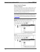
The ID CODE of the CNECI-4A can be changed by using two miniature rotary
switches labeled H and L. These 16-position hexadecimal switches can be set to 0
through F. Attach the CNECI-4A to the control system (verify that the software is
running) and complete the following steps to change the ID CODE:
1. Using a small flat screwdriver, rotate the arrow in the center of switch
H to the first (or most significant) digit or letter of the new ID CODE.
2. Rotate the arrow in the center of switch L to the second (or least
significant) digit or letter of the new ID CODE.
3. The NET indicator illuminates to confirm that the NET ID and ID
CODE are identical.
Operations Guide - DOC. 8149 Electrical Control Interface with AC: CNECI-4A • 7