
Specifications


CRESTRON
Operations Guide - DOC. 8094B Series 3000 Touchpanels •• 9
• Connect the lectern mount configuration directly to the CRESNET II
system via the network cable.
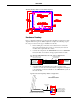
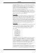
Typical Connection Diagram for Lectern Mount Configuration
CONNECT TO CNMS,
CNRACK, OR CNRACK-D
Refer to the CRESNET II Network Cable
drawing in this section of the Guide.
CONNECT TO SERIAL
PORT OF COMPUTER
Use only for direct connection to PC
to load panels without network.
NOTE: Network termination points are available at the control system power
supply. Network units may also be daisy-chained together. Refer to the latest
revision of the CRESNET II reference manual section on CNPWS power supplies
(Doc. 8091) for wire gauge specifications and connection details.
3. Connect the lectern mount configuration to the serial port of the PC
via the port labeled RS-232. Cable assembly is not supplied.
4. Apply power to the touchpanel and observe illumination of the touch-
sensitive screen. The touchpanel enters RUN MODE and displays a
loaded panel page. To enter SETUP MODE and not RUN MODE,
hold a finger to the touchscreen as power is applied. The user may
configure the unit while in SETUP MODE.
Configuring the Touchpanel
To configure the unit, it may be necessary to access a series of setup screens prior to
viewing run-time screens that are loaded into the touchpanel for normal operation.
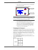
The Main Menu for configuring the touchpanel appears when a finger is held to the
touchscreen as power is applied. Remove your finger when the message "SETUP
MODE" appears on the touchscreen. Holding a finger to the touchscreen for five
seconds after the "SETUP MODE" message is displayed sets the brightness to high
and the contrast to a safe value.
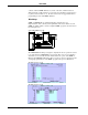
Upon entering SETUP MODE, the Main Screen, shown below, displays four
buttons: TOUCH SCREEN CALIBRATION, DIAGNOSTICS, SETUP, and SAVE
SETUP AND RUN PROGRAM.
Main Menu