
Specifications

Crestron DM-MD6X1 6X1 DigitalMedia™ Switcher
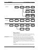
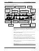
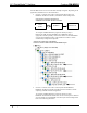
Hardware Connections for the DM-MD6X1 (Rear View)
RGB IN 2:
From Analog and Component
Video Input Sources
DM IN / 24ABG (4-6):
From Outputs of DM Transmitters or
Other DM Devices
VIDEO IN 1:
From YPbPr,
Composite or
S-video Sources
HDMI IN 3:
HDMI Digital Video/
Audio Input
HDMI OUT:
HDMI Digital Video/Audio output
USB HID:
To USB HID
Device
LAN:
10 BASE-T/
100BASE-TX
Ethernet to LAN
Ground
EXT PWR:
Power Input or (via Jumper)
Output to connected DM Devices
100-200V ~2.3A
50/60 Hz:
Power from Line
Voltage
SPDIF IN 1:
From Digital
Audio Output
AUDIO IN (1-2):
Balanced Line Level
Analog Audio
AUDIO OUT:
Balanced Line
Level Audio
DM OUT / 24ABG:
To DigitalMedia Room
Controller or Other DM Devices
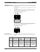
NOTE: If a DM Switcher, or other DM device supplying power, is connected to a
DM IN 4-6 port of the DM-MD6X1, then the +24V wire between the DM device
and the DM-MD6X1 must be disconnected. The A B G wires must remain
connected.
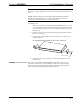
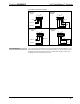
NOTE: Ensure the unit is properly grounded by connecting the chassis ground lug
to an earth ground (building steel).
NOTE: To prevent overheating, do not operate this product in an area that exceeds
the environmental temperature range listed in the table of specifications.
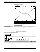
NOTE: For DigitalMedia CAT wiring, use DM-CBL DigitalMedia Cable. Up to
two DM Repeaters (model DM-DR, supplied separately) may be required. Refer to
the Crestron DigitalMedia Design Guide (Doc. 4789) for complete wiring guidelines.
NOTE: For optimum performance, Crestron requires using DM-CBL DigitalMedia
cable, available from Crestron.
NOTE: The minimum cable length required for DM-CBL DigitalMedia cable is 15
feet (~4.6 meters).
Operations Guide – DOC. 6850D 6X1 DigitalMedia™ Switcher: DM-MD6X1 • 21