Crestron TPS-6X-IMCW Interface Module Installation Guide
This document was prepared and written by the Technical Documentation department at: Crestron Electronics, Inc. 15 Volvo Drive Rockleigh, NJ 07647 1-888-CRESTRON Regulatory Compliance As of the date of manufacture, the TPS-6X-IMCW has been tested and found to comply with specifications for CE marking and standards per EMC and Radiocommunications Compliance Labelling. Federal Communications Commission (FCC) Compliance Statement This device complies with part 15 of the FCC Rules.
Crestron TPS-6X-IMCW Interface Module Contents Interface Module for TPS-6X-DS: TPS-6X-IMCW 1 Introduction ............................................................................................................................... 1 Features and Functions ................................................................................................ 1 Specifications .............................................................................................................. 2 Physical Description..
Crestron TPS-6X-IMCW Interface Module Interface Module: TPS-6X-IMCW Introduction The TPS-6X-IMCW is the interface module that is included as standard with the Isys™ TPS-6 Tilt Touchpanel, TPS-6X Series Wireless Touchpanels and TPS-6X-DS and TPS-6XNL-DS Docking Stations. It provides a convenient pluggable connection for the docking station via a single 10-pin RJ-50 jack on its front panel.
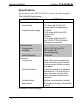
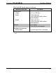
Interface Module Crestron TPS-6X-IMCW Specifications Specifications for the TPS-6X-IMCW are listed in the following table. TPS-6X-IMCW Specifications SPECIFICATION Power Requirements* Power Pack Cresnet Power Usage Environmental Temperature Humidity Heat Dissipation Enclosure Construction Flush Wall Mount Surface Mount Rack Mount DETAILS 0.75 Amps @ 24 Volts DC (power pack sold separately) 0.5 Watts (0.02 Amps @ 24 Volts DC), module only; 18 Watts (0.
Crestron TPS-6X-IMCW Interface Module TPS-6X-IMCW Specifications (Continued) SPECIFICATION Dimensions Height Width Depth Weight Available Accessories Power Pack * DETAILS 4.11 in (105 mm) 1.72 in (44 mm) 1.93 in (49 mm) with surface mount bracket 1.43 in (37 mm) 1.49 in (38 mm) with surface mount bracket 6 oz (162 g) 9 oz (232 g) with bracket 24 Volt Power Pack, Universal May be powered by power pack (sold separately) or Cresnet network power, not both. Installation Guide – DOC.
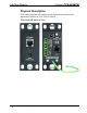
Interface Module Crestron TPS-6X-IMCW Physical Description This section provides information on the connections, controls and indicators available on your TPS-6X-IMCW. TPS-6X-IMCW Physical View 4 • Interface Module: TPS-6X-IMCW Installation Guide – DOC.
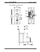
Crestron TPS-6X-IMCW Interface Module TPS-6X-IMCW Overall Dimensions 1.72 in (44 mm) 3 4 4.11 in (105 mm) 6 1 5 2 3 1.67 in (43 mm) 1.43 in (37 mm) 1.24 in (32 mm) 2.62 in (67 mm) 7 5.00 in (127 mm) Installation Guide – DOC.
Interface Module Crestron TPS-6X-IMCW Connectors, Controls & Indicators # CONNECTORS1, CONTROLS & INDICATORS DESCRIPTION 1 TO PANEL (1) 10-wire RJ-50 female; Connection for TPS-6 touchpanel or TPS-6X Series docking station TYPE PIN COLOR 10-Position RJ-50 1 2 Gray Orange/ White Orange 3 4 5 6 7 8 9 10 2 PWR LED 3 PWR 24VDC .
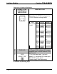
Crestron TPS-6X-IMCW Interface Module Connectors, Controls, & Indicators (Continued) # CONNECTORS1, CONTROLS & INDICATORS 4 VIDEO IN3 + - S S V UNBL BAL 5 NET2 24 Y Z G DESCRIPTION (1) 3-pin 3.5 mm detachable terminal block; Balanced composite video input; Input impedance: 100 Ω nominal; Input level: 1 Vp-p nominal, 1.5 Vp-p maximum; Maximum DC offset: ±2 Volts; Connects to any Crestron CAT5 video out port via CresCAT cable (1) 2-pin 3.
Interface Module Crestron TPS-6X-IMCW Connectors, Controls, & Indicators (Continued) # CONNECTORS1, CONTROLS & INDICATORS 6 LAN 7 GROUND4 DESCRIPTION (1) 8-wire RJ-45; 10/100BASE-T Ethernet port TYPE PIN 8-Position RJ-45 1 2 3 4 5 6 7 8 SIGNALS TD+ TDRD+ N/C N/C RDN/C N/C (1) Flying lead, grounding wire 1. Interface connectors for NET and VIDEO IN ports are provided with the unit. 2. May be powered by power pack (sold separately) or Cresnet network power, not both.
Crestron TPS-6X-IMCW Interface Module Setup Network Wiring When wiring the Cresnet and Ethernet network, consider the following: • Use Crestron Certified Wire. • Use Crestron power supplies for Crestron equipment. • Provide sufficient power to the system. CAUTION: Insufficient power can lead to unpredictable results or damage to the equipment. Please use the Crestron Power Calculator to help calculate how much power is needed for the system (www.crestron.com/calculators).
Interface Module Crestron TPS-6X-IMCW Supplied Hardware The hardware supplied with the TPS-6X-IMCW is listed in the following table.
Crestron TPS-6X-IMCW Interface Module Installation The TPS-6X-IMCW can be installed in either a 1-gang box, rack mounted or mounted to any flat surface using the provided surface mount bracket. Installing in 1-Gang Box To install the TPS-6X-IMCW in a 1-gang box, ensure the unit is mounted into the electrical box as shown in the following illustration.
Interface Module Rack Mounting Crestron TPS-6X-IMCW The TPS-6X-IMCW can be mounted in a rack with other equipment using the four mounting holes on the corners of the interface module, as shown in the following illustration.
Crestron TPS-6X-IMCW Installing on a Level Surface Interface Module To prepare the TPS-6X-IMCW to be mounted onto a level surface, ensure the unit is attached to the surface mount bracket, as shown in the following illustration.
Interface Module Crestron TPS-6X-IMCW Hardware Connections for the TPS-6X-IMCW (Front) TO PANEL: Connect to TPS-6 touchpanel or TPS-6X Series docking station via 10-Pin RJ-50 Cable (Cable Provided with docking station) POWER*: From DC Power Pack * A ferrule dust cap (2017028) is provided to cover the front panel DC power jack when not in use.
Crestron TPS-6X-IMCW Interface Module NOTE: The TPS-6X-IMCW can be powered via the PWR jack on either the front or the back of the unit if the NET port is not being used to power the module. Installation Guide – DOC.
Interface Module Crestron TPS-6X-IMCW Problem Solving Troubleshooting The following table provides corrective action for possible trouble situations. If further assistance is required, please contact a Crestron customer service representative. TPS-6X-IMCW Troubleshooting TROUBLE POSSIBLE CAUSE(S) Device does not function. Device is not receiving sufficient power. PWR LED does not illuminate. Device is not receiving sufficient power. Loss of functionality due to electrostatic discharge.
Crestron TPS-6X-IMCW Interface Module Check Network Wiring Use the Right Wire Calculate Power In order to ensure optimum performance over the full range of your installation topology, Crestron Certified Wire and only Crestron Certified Wire may be used. Failure to do so may incur additional charges if support is required to identify performance deficiencies because of using improper wire. CAUTION: Use only Crestron power supplies for Crestron equipment.
Interface Module Crestron TPS-6X-IMCW NOTE: All Crestron certified Cresnet wiring must consist of two twisted pairs. One twisted pair is the +24V conductor and the GND conductor and the other twisted pair is the Y conductor and the Z conductor. Strip and Tin Wire When daisy-chaining Cresnet units, strip the ends of the wires carefully to avoid nicking the conductors. Twist together the ends of the wires that share a pin on the network connector and tin the twisted connection.
Crestron TPS-6X-IMCW Interface Module Return and Warranty Policies Merchandise Returns / Repair Service 1. No merchandise may be returned for credit, exchange or service without prior authorization from CRESTRON. To obtain warranty service for CRESTRON products, contact an authorized CRESTRON dealer. Only authorized CRESTRON dealers may contact the factory and request an RMA (Return Merchandise Authorization) number.
Crestron Electronics, Inc. 15 Volvo Drive Rockleigh, NJ 07647 Tel: 888.CRESTRON Fax: 201.767.7576 www.crestron.com Installation Guide – DOC. 6874B (2025142) 01.10 Specifications subject to change without notice.