Crestron FT-PWR-D & FT-PWR-D-LG FlipTop Power Centers, Dual AC Outlets Operations & Installation Guide
This document was prepared and written by the Technical Documentation department at: Crestron Electronics, Inc. 15 Volvo Drive Rockleigh, NJ 07647 1-888-CRESTRON Regulatory Compliance This product conforms to UL STD 962A; certified to CSA STD C22.2 No. 21. As of the date of manufacture, the FT-PWR-D and FT-PWR-D-LG have been tested and found to comply with specifications for CE marking and standards per EMC and Radiocommunications Compliance Labelling.
Crestron FT-PWR-D & FT-PWR-D-LG FlipTop Power Centers Contents FlipTop Power Centers, Dual AC Outlets: FT-PWR-D & FT-PWR-D-LG 1 Introduction ............................................................................................................................... 1 Features and Functions ................................................................................................ 1 Applications.......................................................................................................
Crestron FT-PWR-D & FT-PWR-D-LG FlipTop Power Centers FlipTop Power Centers, Dual AC Outlets: FT-PWR-D & FT-PWR-D-LG Introduction The FT-PWR-D and FT-PWR-D-LG FlipTop Power Centers provide an elegant connectivity solution in a stylish flush mount tabletop package. Beneath the "FlipTop" lid, the cable storage compartment keeps interface cables at the ready for plugging in computers, AV sources, and a host of other devices.
FlipTop Power Centers Crestron FT-PWR-D & FT-PWR-D-LG Cable Storage Compartment The FT-PWR-D/-LG provides for extensive connectivity through an easy pull-out cable storage mechanism to support a wide range of applications and signal types. Eight grommeted holes are provided in the bottom plate, allowing for smooth pass-through of virtually any type of AV, communication, control, or data cable (cables not included).
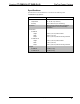
Crestron FT-PWR-D & FT-PWR-D-LG FlipTop Power Centers Specifications Specifications for the FT-PWR-D/-LG are listed in the following table. FT-PWR-D/-LG Specifications SPECIFICATION DETAILS Environmental Temperature 41º to 104º F (5º to 40º C) Humidity 10% to 90% RH (non-condensing) Enclosure Black painted metal with black anodized or brushed aluminum cover; flush tabletop mountable Dimensions FT-PWR-D Height 5.39 in (137 mm) with lid closed Width 6.75 in (171 mm) Depth 5.
FlipTop Power Centers Crestron FT-PWR-D & FT-PWR-D-LG Physical Description This section provides information on the connections, controls, and indicators available on your FT-PWR-D/-LG. FT-PWR-D Physical View FT-PWR-D-LG Physical View NOTE: Cables not included. 4 • FlipTop Power Centers: FT-PWR-D & FT-PWR-D-LG Operations & Installation Guide – DOC.
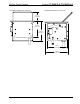
Crestron FT-PWR-D & FT-PWR-D-LG FlipTop Power Centers FT-PWR-D Overall Dimensions (Top View) 5.08 in (129 mm) 5.71 in (145 mm) 6.75 in (171 mm) FT-PWR-D Overall Dimensions (Front View) FT-PWR-D (Bottom View) 5.16 in (131 mm) 6.25 in (159 mm) Operations & Installation Guide – DOC.
FlipTop Power Centers Crestron FT-PWR-D & FT-PWR-D-LG FT-PWR-D Overall Dimensions (Rear View) FT-PWR-D Overall Dimensions (Side View) 2.31 in (59 mm) 4.31 in (110 mm) 5.39 in (137 mm) 4.63 in (118 mm) 5.21 in (132 mm) 6 • FlipTop Power Centers: FT-PWR-D & FT-PWR-D-LG Operations & Installation Guide – DOC.
Crestron FT-PWR-D & FT-PWR-D-LG FlipTop Power Centers FT-PWR-D-LG Overall Dimensions (Top View) 6.00 in (152 mm) 6.55 in (166 mm) 7.67 in (195 mm) FT-PWR-D-LG Overall Dimensions (Front View) FT-PWR-D-LG (Bottom View) 6.08 in (154 mm) 7.17 in (182 mm) Operations & Installation Guide – DOC.
FlipTop Power Centers Crestron FT-PWR-D & FT-PWR-D-LG FT-PWR-D-LG Overall Dimensions (Rear View) FT-PWR-D-LG Overall Dimensions (Side View) 2.64 in (67 mm) 4.75 in (121 mm) 5.76 in (146 mm) 5.51 in (140 mm) 6.04 in (153 mm) FT-PWR-D/-LG (Front Face View) 1 8 • FlipTop Power Centers: FT-PWR-D & FT-PWR-D-LG Operations & Installation Guide – DOC.
Crestron FT-PWR-D & FT-PWR-D-LG FlipTop Power Centers FT-PWR-D/-LG (Bottom View) 2 Connectors, Controls, & Indicators # CONNECTORS, CONTROLS, & INDICATORS 1 125V~50/60Hz 10A (2) Grounded AC sockets, AC power pass-through outlets; Maximum load: 10 Amps (total) @ 120 Volts AC, 50/60 Hz 2 125V~50/60Hz 10A (1) 9 foot grounded AC line cord; passes through to front panel AC power outlets Operations & Installation Guide – DOC.
FlipTop Power Centers Crestron FT-PWR-D & FT-PWR-D-LG Setup Installation NOTE: To prevent overheating, do not operate this product in an area that exceeds the environmental temperature range listed in the specifications table. Consideration must be given if installed inside a closed desk or in a closed podium since the operating ambient temperature of these environments may be greater than the room ambient temperature. Contact with thermal insulating materials should be avoided on all sides of the unit.
Crestron FT-PWR-D & FT-PWR-D-LG FlipTop Power Centers Cable Support Plate Installation When selecting cables for installation in the FT-PWR-D/-LG, cable connector length and strain relief diameter are important considerations. • If the connector is too long, it can interfere with cover operation. • If the width of the cable strain relief is too similar to the bushing inside diameter, the bushing can trap the cable. NOTE: Do not use the cable support plate without the bushings.
FlipTop Power Centers Crestron FT-PWR-D & FT-PWR-D-LG Cables Threaded Through the Cable Plate NOTE: Allow approximately 40 inches clearance for cables. Cables passed through cable support plate. NOTE: Ensure that any cables you install have sufficient clearance to enable smooth movement. Allow approximately 40 inches (~ 1 meter) from the top surface of the FlipTop box. Surface Mounting The FT-PWR-D/-LG is designed to mount in a horizontal surface, such as a desk top, lectern, or podium.
Crestron FT-PWR-D & FT-PWR-D-LG FlipTop Power Centers Example of the Cutout Dimensions for the FT-PWR-D-LG (Not Actual Cutout Template) 7 1/4 in (184 mm) 6 1/8 in (156 mm) MAXIMUM RADIUS 1/8 IN (4 MM) NOTE: Be sure to feed the attached power cord and all required cables through the mounting hole before inserting the FT-PWR-D/-LG.
FlipTop Power Centers Crestron FT-PWR-D & FT-PWR-D-LG Mounting Bracket Screw Locations Screws (4) #06-32 X 3/16" (Pre-Installed) Screws (4) #06-32 X 3/16" (2007204) Surface Cutout 3. Thread a small portion of the #10-32 x 2” screws (2007293) into the mounting brackets (two screws per bracket). Refer to the illustration on the following page. 4. Slide the mounting brackets over the #06-32 screws and tighten the #06-32 screws.
Crestron FT-PWR-D & FT-PWR-D-LG FlipTop Power Centers Mounting Bracket Installation 5. Turn the four #10-32 screws equally until they contact the underside of the mounting surface enough to secure the unit. DO NOT OVER-TIGHTEN. CAUTION: Do not over-tighten the #10-32 screws as this may damage the surface and/or the unit. FT-PWR-D (Mounting Brackets Installed) Operations & Installation Guide – DOC.
FlipTop Power Centers Crestron FT-PWR-D & FT-PWR-D-LG FT-PWR-D-LG (Mounting Brackets Installed) Hardware Hookup Hookup consists of simply plugging the line cord into an appropriate outlet. NOTE: The maximum continuous current from equipment under any external load conditions shall not exceed a current limit that is suitable for the minimum wire gauge used in interconnecting cables. The ratings on the connecting unit's supply input should be considered to prevent overloading the wiring.
Crestron FT-PWR-D & FT-PWR-D-LG FlipTop Power Centers Operation The spring-loaded lid is opened by pressing briefly and releasing it. Cables are stored neatly beneath the lid when not in use to keep out debris and dust. The lid opens 135 degrees, allowing full access to cables and power inside. Beneath the lid, a recessed compartment with eight grommeted holes through the bottom plate allows any type of AV, communication, data or control cables to be instantly available for connection to your devices.
FlipTop Power Centers Crestron FT-PWR-D & FT-PWR-D-LG Problem Solving Troubleshooting The following table provides corrective action for possible trouble situations. If further assistance is required, please contact a Crestron customer service representative. FT-PWR-D/-LG Troubleshooting TROUBLE POSSIBLE CAUSE(S) Device connected to the AC socket is not working. CORRECTIVE ACTION Lack of, or insufficient, power to AC socket. Provide appropriate power to the line cord. Device is not receiving power.
Crestron FT-PWR-D & FT-PWR-D-LG FlipTop Power Centers Return and Warranty Policies Merchandise Returns / Repair Service 1. No merchandise may be returned for credit, exchange or service without prior authorization from CRESTRON. To obtain warranty service for CRESTRON products, contact an authorized CRESTRON dealer. Only authorized CRESTRON dealers may contact the factory and request an RMA (Return Merchandise Authorization) number.
Crestron Electronics, Inc. 15 Volvo Drive Rockleigh, NJ 07647 Tel: 888.CRESTRON Fax: 201.767.7576 www.crestron.com Operations & Installation Guide – DOC. 6640C (2019709) 06.10 Specifications subject to change without notice.