Crestron FT-PWR-D-B & FT-PWR-D-BALUM FlipTop Power Center with Dual AC Operations & Installation Guide
This document was prepared and written by the Technical Documentation department at: Crestron Electronics, Inc. 15 Volvo Drive Rockleigh, NJ 07647 1-888-CRESTRON All brand names, product names and trademarks are the property of their respective owners. ©2008 Crestron Electronics, Inc.
Crestron FT-PWR-D-B & FT-PWR-D-BALUM FlipTop Power Center Contents FlipTop Power Center: FT-PWR-D-B & FT-PWR-D-BALUM 1 Introduction ............................................................................................................................... 1 Features and Functions ................................................................................................ 1 Specifications .............................................................................................................
Crestron FT-PWR-D-B & FT-PWR-D-BALUM FlipTop Power Center FlipTop Power Center: FT-PWR-D-B & FT-PWR-D-BALUM Introduction Features and Functions The FT-PWR-D-B and FT-PWR-D-BALUM provide an elegant connectivity solution in a stylish flush mount tabletop package. Beneath the "FlipTop" lid, the cable storage compartment keeps installed interface cables (not included) at the ready for plugging in computers, AV sources, communication, control, or data cable.
FlipTop Power Center Crestron FT-PWR-D-B & FT-PWR-D-BALUM AC Power Outlets For complete connectivity, two AC power receptacles are included within the FlipTop compartment. Specifications Specifications for the FT-PWR-D are listed in the following table.
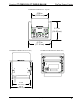
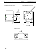
Crestron FT-PWR-D-B & FT-PWR-D-BALUM FlipTop Power Center FT-PWR-D Overall Dimensions – Top View 5.08 in (12.90 cm) 5.71 in (14.50 cm) 6.75 in (17.15 cm) FT-PWR-D Overall Dimensions (Front View) FT-PWR-D Overall Dimensions (Bottom View) 5.16 in (13.10 cm) 6.25 in (15.88 cm) Operations Guide – DOC.
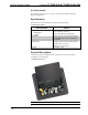
FlipTop Power Center Crestron FT-PWR-D-B & FT-PWR-D-BALUM FT-PWR-D Overall Dimensions (Rear View) FT-PWR-D Overall Dimensions (Side View) 2.31 in (5.88 cm) 4.31 in (10.95 cm) 5.39 in (13.69 cm) 4.63 in (11.76 cm) 5.21 in (13.23 cm) FT-PWR Front Face View 1 4 • FlipTop Power Center: FT-PWR-D-B & FT-PWR-D-BALUM Operations Guide – DOC.
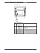
Crestron FT-PWR-D-B & FT-PWR-D-BALUM FlipTop Power Center FT-PWR-D Bottom View 2 Connectors, Controls, & Indicators # 1 2 Operations Guide – DOC. 6640A CONNECTORS, CONTROLS, & INDICATORS DESCRIPTION (2) Grounded AC sockets, AC power pass through outlets; Maximum load: 10 Amps @ 120 Volts AC, 50/60 Hz (1) 9 foot grounded AC line cord; passes through to front panel AC power outlets.
FlipTop Power Center Crestron FT-PWR-D-B & FT-PWR-D-BALUM Industry Compliance As of the date of manufacture, the FT-PWR-D has been tested and found to comply with specifications for CE marking and standards per EMC and Radiocommunications Compliance Labelling. NOTE: This device complies with part 15 of the FCC rules.
Crestron FT-PWR-D-B & FT-PWR-D-BALUM FlipTop Power Center Setup Installation NOTE: To prevent overheating, do not operate this product in an area that exceeds the environmental temperature range listed in the specifications table. Consideration must be given if installed inside a closed desk or in a closed podium since the operating ambient temperature of these environments may be greater than the room ambient. Contact with thermal insulating materials should be avoided on all sides of the unit.
FlipTop Power Center Crestron FT-PWR-D-B & FT-PWR-D-BALUM Cable Support Plate Installation When selecting cables for installation in the FT-PWR-D, cable connector length and strain relief diameter are important considerations. • If the connector is too long, it can interfere with cover operation. • If the width of the cable strain relief is too similar to the bushing inside diameter, the bushing can trap the cable. NOTE: Do not use the cable support plate without the bushings.
Crestron FT-PWR-D-B & FT-PWR-D-BALUM FlipTop Power Center Cables Threaded Through the Cable Plate NOTE: Ensure that any cables you install have sufficient clearance to enable smooth movement. Allow approximately 40 inches (102 cm) from the top surface of the FlipTop box. Mounting to Surface The FT-PWR-D is designed to mount in a horizontal surface, such as a desk top, lectern, or podium. The following diagram illustrates the required opening size to accommodate the FT-PWR-D.
FlipTop Power Center Crestron FT-PWR-D-B & FT-PWR-D-BALUM Mounting Parts Supplied DESCRIPTION Screw #6-32, 3/16” L, Pan Head, Phillips PART NUMBER QUANTITY 2007204 8 Screw #10-32, 2” L, Pan Head, Phillips 2007293 4 Mounting Bracket 2013224 2 1. Install the eight supplied #6-32 screws, but do not tighten (four on the front side and four on the rear side). These will be used to secure the front and rear mounting brackets. 2. Position the FT-PWR-D in the mounting hole.
Crestron FT-PWR-D-B & FT-PWR-D-BALUM FlipTop Power Center Mounting Bracket Installation 5. Turn the four #10 screws equally until they contact the underside of the mounting surface enough to secure the unit. DO NOT OVER TIGHTEN. CAUTION: Do not over-tighten the #10 screws as this may damage the surface and/or the unit. Mounting Brackets Installed 7.21 in (18.
FlipTop Power Center Crestron FT-PWR-D-B & FT-PWR-D-BALUM Operation The spring-loaded lid is opened by pressing briefly and releasing it. Cables are stored neatly beneath the lid when not in use to keep out debris and dust. The lid opens 135 degrees, allowing full access to cables and power inside. Beneath the lid, a recessed compartment with eight grommeted holes through the bottom plate allows any type of AV, communication, data or control cables to be instantly available for connection to your devices.
Crestron FT-PWR-D-B & FT-PWR-D-BALUM FlipTop Power Center Problem Solving Troubleshooting The following table provides corrective action for possible trouble situations. If further assistance is required, please contact a Crestron customer service representative. FT-PWR-D Troubleshooting TROUBLE POSSIBLE CAUSE(S) Device connected to the AC socket is not working. Lack of, or insufficient power to, AC socket. CORRECTIVE ACTION Provide appropriate power to the line cord.
FlipTop Power Center Crestron FT-PWR-D-B & FT-PWR-D-BALUM Return and Warranty Policies Merchandise Returns / Repair Service 1. No merchandise may be returned for credit, exchange, or service without prior authorization from CRESTRON. To obtain warranty service for CRESTRON products, contact an authorized CRESTRON dealer. Only authorized CRESTRON dealers may contact the factory and request an RMA (Return Merchandise Authorization) number.
Crestron FT-PWR-D-B & FT-PWR-D-BALUM FlipTop Power Center This page is intentionally left blank. Operations Guide – DOC.
Crestron Electronics, Inc. 15 Volvo Drive Rockleigh, NJ 07647 Tel: 888.CRESTRON Fax: 201.767.7576 www.crestron.com Operations & Installation Guide – DOC. 6640A (2019709) 03.08 Specifications subject to change without notice.