Crestron C2N/C2NI-CB Series Cameo™ Keypads Operations & Installation Guide
This document was prepared and written by the Technical Documentation department at: Crestron Electronics, Inc. 15 Volvo Drive Rockleigh, NJ 07647 1-888-CRESTRON All brand names, product names and trademarks are the property of their respective owners. ©2006 Crestron Electronics, Inc.
Crestron C2N/C2NI-CB Series Cameo™ Keypads Contents Cameo™ Keypads: C2N/C2NI-CB Series 1 Introduction......................................................................................1 Features and Functions ..........................................................1 Specifications.........................................................................3 Physical Description ..............................................................4 Industry Compliance...........................................
Cameo™ Keypads Crestron C2N/C2NI-CB Series ™ Cameo Keypads: C2N/C2NI-CB Series Introduction Features and Functions The Crestron® C2N/C2NI-CB Series Cameo keypads are a new generation of wall-mounted user interfaces that can be part of any Crestron total solution control system network (Cresnet®).
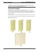
Cameo™ Keypads Crestron C2N/C2NI-CB Series The basic Cameo keypad colors are black, white, and almond. The keypad’s colors and finishes can be used to accent a home’s colors, wall coverings, or décor. Additional designer colors are available. (Contact a Crestron customer service representative for details.
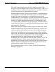
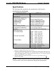
Crestron C2N/C2NI-CB Series Cameo™ Keypads Specifications The following table summarizes the specifications of the keypads. Specifications for the Keypads SPECIFICATION Cresnet Power Usage Default Net ID Control System Update Files 1, 2, 3 2-Series Control System CNMSX-AV/PRO CNRACKX/-DP CEN/CN-TVAV ST-CP C2N-CB-Series Firmware Environmental Temperature Humidity Overall Dimensions: Flush Mount Model Decorator Style Model UK Style Model Weight 1. 2. 3. 4. DETAILS 3 Watts (0.
Cameo™ Keypads Crestron C2N/C2NI-CB Series (CAIP) only. New users may be required to register to obtain access to certain areas of the site (including the FTP site). Physical Description The number of active switches on a keypad can be 1, 2, 3, 4, 5, or 6. Active switches and spacers can be mixed and arranged as needed to suit a particular application. LEDs along the side of the keypad identify the active switches. Each keypad has a mini Cresnet network port labeled 24 Y Z G.
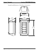
Crestron C2N/C2NI-CB Series Cameo™ Keypads The previous illustration shows three of many possible flush mount configurations: two double-row switches with two single-row switches (A); three double-row switches (B); and six single-row switches (C), all with the LED indicators on the left. A UK-style configuration with three double-row switches is also shown (D). The button caps are tapered and are arranged here in a shingle style with the narrow part of the button cap at the top.
Cameo™ Keypads Crestron C2N/C2NI-CB Series Keypad Overall Dimensions – Flush Mount Configuration 1.73 in (4.38 cm) 1.52 in (3.86 cm) 2.06 in (5.23 cm) 3.20 in (8.13 cm) 6 • Cameo™ Keypads: C2N/C2NI-CB Series Operations & Installation Guide - DOC.
Cameo™ Keypads Crestron C2N/C2NI-CB Series Keypad Overall Dimensions – Decorator Mount Configuration 1.52 in (3.86 cm) 1.80 in (4.56 cm) 4.12 in (10.47 cm) Operations & Installation Guide - DOC.
Cameo™ Keypads Crestron C2N/C2NI-CB Series Keypad Overall Dimensions – UK-Style Configuration 1.14 in (2.89 cm) 1.52 in (3.86 cm) 0.30 in (0.76 cm) 3.38 in (8.58 cm) 3.38 in (8.58 cm) Industry Compliance As of the date of manufacture, the keypads have been tested and found to comply with specifications for CE marking and standards per EMC and Radiocommunications Compliance Labelling. NOTE: This device complies with part 15 of the FCC rules.
Cameo™ Keypads Crestron C2N/C2NI-CB Series Setup Network Wiring CAUTION: In order to ensure optimum performance over the full range of your installation topology, Crestron Certified Wire, and only Crestron Certified Wire, should be used. Failure to do so may incur additional charges if support is required to identify performance deficiencies as a result of using improper wire. CAUTION: Use only Crestron power supplies for Crestron equipment.
Cameo™ Keypads Crestron C2N/C2NI-CB Series NOTE: All Crestron certified Cresnet wiring must consist of two twisted pairs. One twisted pair is the +24V conductor and the GND conductor, and the other twisted pair is the Y conductor and the Z conductor. NOTE: When daisy-chaining Cresnet units, strip the ends of the wires carefully to avoid nicking the conductors. Twist together the ends of the wires that share a pin on the network connector, and tin the twisted connection.
Cameo™ Keypads Crestron C2N/C2NI-CB Series The Crestron Toolbox provides several methods to easily set or change device Net IDs for any device on the network. The following method permits you to change the Net ID of any device in the network through the “Network Device Tree” window. NOTE: This method prevents you from setting duplicate IDs.
Cameo™ Keypads Crestron C2N/C2NI-CB Series Network Device Tree – Sub-Menu 5. Enter a new Net ID and press Enter. Enter New Net ID 6. Repeat this procedure for each additional network device requiring a Net ID change.
Cameo™ Keypads Crestron C2N/C2NI-CB Series Installation consists of connecting the unit to the Cresnet system, and then mounting it directly to the mounting surface or to a back box, depending on the keypad configuration. The following items are required for all installations: • Cresnet network cable (not supplied) • No.
Cameo™ Keypads Crestron C2N/C2NI-CB Series 3. Hold the bezel and rear housing together and install and tighten the two supplied Phillips pan head, 4-40 x 3/16” cover screws (black) into the rear housing and switch assembly, as shown in the following illustration. 4. Press each button to be certain that you feel the press and release to ensure that the button caps move freely. LED Holes Bezel Button Caps and Spacers Cover Screw Plastic Button Support LEDs Rear Housing and Switch Assembly 5.
Cameo™ Keypads Crestron C2N/C2NI-CB Series 6. Use the supplied template to prepare the hole in the wall. (Refer to the Appendix on page 40 for an illustration of the template.) After the Cresnet network wiring has been installed and verified, use the following procedure to install the keypad in the prepared hole. NOTE: Be very careful when cutting the hole. There are no adjustments for alignment with the spring clamp. 7.
Cameo™ Keypads Crestron C2N/C2NI-CB Series Decorator Mounting Installation The keypad for Decorator mounting installation is supplied partially assembled along with several items as listed in the following table.
Cameo™ Keypads Crestron C2N/C2NI-CB Series LED Holes Bezel Assembly Ground Wire Cover Screw Button Caps and Spacers Plastic Button Support LEDs Bracket Rear Housing and Switch Assembly 3. Hold the bezel and rear housing together 4. Install and tighten the two supplied Phillips pan head, 4-40 x 3/16” cover screws (black), as shown in the illustration. 5. Press each button to be certain that you feel the press and release to ensure that the button caps move freely.
Cameo™ Keypads Crestron C2N/C2NI-CB Series 5. Attach the desired Decora style faceplate (not supplied). 6. Turn the Cresnet system power ON. UK-Style Mounting Installation The keypad for UK-style mounting installation is supplied partially assembled along with several items as listed in the following table.
Cameo™ Keypads Crestron C2N/C2NI-CB Series Supplied Parts/Assemblies – UK-Style Mounting (continued) QTY ITEM DESCRIPTION 2 Screws, Black, Phillips pan head, 4-40 x 3/16” Used to attach the bezel assembly to the keypad rear housing and switch assembly 6 Single row button cap Switch cover for a single row switch 3 Double row button cap Switch cover for two switches that function as one 2 Triple row button cap Switch cover for three switches that function as one 2 Single row spacer Switch c
Cameo™ Keypads Crestron C2N/C2NI-CB Series 4. Press each button to be certain that you feel the press and release to ensure that the button caps move freely. The keypad can be mounted directly to a mounting surface or it can be mounted to a back box. In both cases, you can choose to have mounting screws visible or hidden. Mounting to the Mounting Surface Use the supplied template to prepare the hole in the wall. (Refer to the Appendix on page 40 for an illustration of the template.
Cameo™ Keypads Crestron C2N/C2NI-CB Series 2. Turn Cresnet system power OFF, and connect the Cresnet cable to the keypad’s Cresnet port, using the supplied mating connector. 3. Insert the keypad into the hole and press the bezel against the plastic wall plate until it snaps securely into position. 4. Turn the Cresnet system power On. If the keypad needs to be removed from the wall, there are two slots on one edge of the bezel (visible in the figure on page 22).
Cameo™ Keypads 22 • Cameo™ Keypads: C2N/C2NI-CB Series Crestron C2N/C2NI-CB Series Operations & Installation Guide - DOC.
Cameo™ Keypads Crestron C2N/C2NI-CB Series Programming Software Have a question or comment about Crestron software? Answers to frequently asked questions (FAQs) can be viewed in the Online Help section of the Crestron website. To post a question or view questions you have submitted to Crestron’s True Blue Support, log in at http://support.crestron.com. First-time users will need to establish a user account.
Cameo™ Keypads Crestron C2N/C2NI-CB Series • (Optional) SystemBuilder version 2.0 or later with SystemBuilder Templates version 2.0.1or later. Requires the following software versions: o PC with Windows 2000 or XP o SIMPL Windows version 2.06.20 or later with library update file 352 or later. Requires SIMPL+ Cross Compiler version 1.1. o Crestron database 17.3.3 or later o Vision Tools Pro-e 3.3.4.0 or later o Crestron Toolbox 1.01.11 or later o Engraver 2.5 or later • (Optional) D3 Pro version 2.
Crestron C2N/C2NI-CB Series Cameo™ Keypads Crestron D3 Pro similarly offers automatic programming for lighting, HVAC, and security. Both Crestron SystemBuilder and D3 Pro are fully integrated with Crestron's suite of software development tools, including SIMPL Windows, VT Pro-e, and the Crestron Database. Both access these tools behind the scenes, enabling you to easily create robust systems. Programming with SIMPL Windows NOTE: The following assumes that the reader has knowledge of SIMPL Windows.
Cameo™ Keypads Crestron C2N/C2NI-CB Series Expanded PRO2 System Tree C2Net-Device Slot in Configuration Manager To incorporate a Cameo keypad into the system, drag the C2N-CB from the Wired Keypad folder of the Device Library and drop it in System Views. The PRO2 system tree displays the C2N-CB in Slot 9, with a default Net ID of 25 as shown in the following illustration.
Cameo™ Keypads Crestron C2N/C2NI-CB Series Setting the Net ID in Device Settings Double-click the C2N-CB icon in the upper pane to open the “Device Settings” window. This window displays C2N-CB device information. Select the Net ID tab to change the Net ID, as shown in the following figure. C2N-CB Device Settings Window NOTE: This procedure sets the Net ID for the C2N-CB in the program only. It does not automatically set the Net ID for the keypad itself.
Cameo™ Keypads Crestron C2N/C2NI-CB Series Cameo Keypad Button and Feedback LED Arrangement In cases where it is desirable to mount the keypad with the feedback LEDs on the right, programmers will have to take into account that physically, button 6 is now at the top, button 1 is at the bottom, and that the right and left switch positions are reversed. Bear in mind, however, that when combining buttons in this orientation, the usual programming constraints still apply.
Cameo™ Keypads Crestron C2N/C2NI-CB Series Uploading and Upgrading NOTE: Crestron recommends that you use the latest software and that each device contains the latest firmware to take advantage of the most recently released features. Please check the Crestron website (http://www.crestron.com/updates) for the latest versions of software and firmware. New users are required to register to obtain access to this site.
Cameo™ Keypads Crestron C2N/C2NI-CB Series Typical Connection Diagram when Uploading 1. Open Crestron Toolbox and click Tools | Manage Address Book to display a list of available devices. Select Serial on COM1 as the connection type. Serial on COM1 is an entry in the DefaultAddressBook that is included with Crestron Toolbox. The PC communication settings specified here should match the protocol that the control processor expects. The usual settings are as follows: • Port = COM 1 through COM 8.
Cameo™ Keypads Crestron C2N/C2NI-CB Series “Address Book” Window – Serial Setup 2. After setting the correct parameters, click OK to return to the Crestron Toolbox main window. 3. Click Tools | Network Device Tree, or click the network device tree icon to display the devices in the system. Select Serial on COM1 from the drop down list if it is not already selected. If communication is successful, the network devices that are connected to the control system are displayed.
Cameo™ Keypads Crestron C2N/C2NI-CB Series managed is selected. Right-click the desired Net ID to open the sub-menu. This menu provides a wide range of operations, including; change the Net ID, open text console, and, through the sub-sub menu, additional functions such as updating firmware and serial number conversion. Network Device Tree Sub-Menu -Functions NOTE: Toolbox displays a customized list of functions depending on the type of device with which it is communicating.
Cameo™ Keypads Crestron C2N/C2NI-CB Series 2. Open Crestron Toolbox. 3. Select Tools | System Info. Crestron Toolbox – Tools | System Info 4. When the “System Info” window appears and you are connected to the control system, the Functions option becomes available from the menu bar. 5. Select Functions | SIMPL Program. The “SIMPL Program” window contains information about the currently loaded SIMPL program (if any), and permits you to stop, start, erase, retrieve, and upload a SIMPL program.
Cameo™ Keypads Crestron C2N/C2NI-CB Series “SIMPL Program” Window 6. Click the Browse button to browse for a new compiled (.spz) program file in the “Open” window. “Open” Window 34 • Cameo™ Keypads: C2N/C2NI-CB Series Operations & Installation Guide - DOC.
Cameo™ Keypads Crestron C2N/C2NI-CB Series 7. Select a file and click Open. When the “SIMPL Program” window re-opens click Send. Firmware Upgrade A firmware upgrade file has the extension .upg. To take advantage of all the Cameo keypad features, it is important that the unit contains the latest firmware available. Please check the Crestron website for the latest version of firmware.
Cameo™ Keypads Crestron C2N/C2NI-CB Series “Firmware” Window 6. Click Browse to display the Open window to locate the desired firmware (.upg) file. Locate Firmware in the “Open” Window 7. Click Open to return to the “Firmware” window, and click Send to transfer the file. The File Transfer window monitors the transfer of the file and gives you the option of canceling the transfer. 36 • Cameo™ Keypads: C2N/C2NI-CB Series Operations & Installation Guide - DOC.
Crestron C2N/C2NI-CB Series Cameo™ Keypads “File Transfer” Window 8. When the transfer is complete, the “Firmware” window reopens indicating the new firmware version. Click Close after the firmware has been transferred. Operations & Installation Guide - DOC.
Cameo™ Keypads Crestron C2N/C2NI-CB Series Problem Solving Troubleshooting The table below provides corrective action for possible trouble situations. If further assistance is required, please contact a Crestron customer service representative. Keypad Troubleshooting TROUBLE POSSIBLE CAUSE(S) CORRECTIVE ACTION The keypad does not function. The wrong power supply is being used. Use a Crestron power supply. The unit is not receiving power, or is receiving insufficient power.
Crestron C2N/C2NI-CB Series Cameo™ Keypads Future Updates As Crestron improves functions, adds new features, and extends the capabilities of the Cameo keypad, additional information and programming examples may be made available as manual updates. These updates are solely electronic and serve as intermediary supplements prior to the release of a complete technical documentation revision. Check the Crestron website periodically for manual update availability and its relevance.
Cameo™ Keypads Crestron C2N/C2NI-CB Series Appendix: Template for Flush Mounting Hole The following figure (not to scale) illustrates the supplied template used to prepare the hole in the wall or other mounting surface for the flush mounting style Cameo keypad. NOTE: Use only the original template, not a photocopy, to prepare the hole. Photocopies usually alter the size of the image slightly, which would make the hole the wrong size.
Cameo™ Keypads Crestron C2N/C2NI-CB Series Return and Warranty Policies Merchandise Returns / Repair Service 1. No merchandise may be returned for credit, exchange, or service without prior authorization from CRESTRON. To obtain warranty service for CRESTRON products, contact an authorized CRESTRON dealer. Only authorized CRESTRON dealers may contact the factory and request an RMA (Return Merchandise Authorization) number.
Cameo™ Keypads Crestron C2N/C2NI-CB Series This page intentionally left blank. 42 • Cameo™ Keypads: C2N/C2NI-CB Series Operations & Installation Guide - DOC.
Crestron C2N/C2NI-CB Series Cameo™ Keypads This page intentionally left blank. Operations & Installation Guide - DOC.
Crestron Electronics, Inc. 15 Volvo Drive Rockleigh, NJ 07647 Tel: 888.CRESTRON Fax: 201.767.7576 www.crestron.com Operations & Installation Guide - DOC. 6346A (2012599) 02.06 Specifications subject to change without notice.