
User Guide

Cameo
™
Keypads Crestron C2N/C2NI-CB Series
Decorator Mounting Installation
The keypad for Decorator mounting installation is supplied partially
assembled along with several items as listed in the following table.
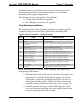
Supplied Parts/Assemblies – Decorator Mounting
QTY ITEM DESCRIPTION
1 Rear housing and switch assembly Rear housing with switch circuitry attached
1 Bezel assembly Bezel and metal plate assembly, with ground wire
1
4-pin female mini network
connector
Used to connect Cresnet network cable to the keypad
2
Screws, Black, Phillips pan head,
4-40 x 3/16”
Used to attach the bezel assembly to the keypad rear
housing and switch assembly
6 Single row button cap Switch cover for a single row switch
3 Double row button cap Switch cover for two switches that function as one
2 Triple row button cap Switch cover for three switches that function as one
2 Single row spacer Switch cover for single non-operational switch
1 Double row spacer Switch cover for two non-operational switches
1 Triple row spacer Switch cover for three non-operational switches
1 Plastic button support
Used to hold the button caps/spacers together in
position
2
Screws, Steel, Phillips, pan head,
6-32 x 7/8”
Used to attach the assembled keypad to a back box
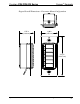
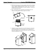
Assemble the keypad as described in the following steps. Refer to the
accompanying illustrations.
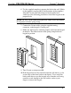
1. Arrange the button caps
and/or spacers in position
according to the program
plan. Attach the plastic
button support to the
button caps/spacers, and
put the assembled parts in
place on the rear housing
and switch assembly.
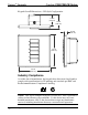
2. Carefully position the
bezel assembly, LED edge
first, down and over the
button caps/spacers and
rotate slightly into
position on the rear
housing and switch assembly.
Button Caps
and Spacers
Plastic
Button
Support
Rear Housing
and Switch
Ass’y
16 • Cameo™ Keypads: C2N/C2NI-CB Series Operations & Installation Guide - DOC. 6346A