
User Guide

FlipTop Control Center with Cresnet
®
Crestron C2N-FTB
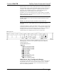
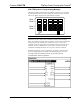
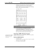
C2N-FTB Buttons – Signal Descriptions
SIGNAL TYPE AND NAME DESCRIPTION
Digital Outputs:
Button presses/vertical pair
<Press1>, <Press6>
Button presses/vertical pair
<Press2>, <Press7>
Button presses/vertical pair
<Press3>, <Press8>
Button presses/vertical pair
<Press4>, <Press9>
Button presses/vertical pair
<Press5>, <Press10>
Button presses/vertical pair
<Press11>, <Press16>
Button presses/vertical pair
<Press12>, <Press17>
Button presses/vertical pair
<Press13>, <Press18>
Button presses/vertical pair
<Press14>, <Press19>
Button presses/vertical pair
<Press15>, <Press20>
Indicates that the corresponding button has been
pressed. The signal remains high for the duration
of the button press.
If the FlipTop cover is not fully open the buttons
are disabled and the unit will not report any button
presses, and will release any button that is already
pressed. The status of the cover is given by the
<FlipTopOpen> output.
If two buttons are combined to form one larger
button, the same signal should be attached to both
button presses.
High/1 = Button pressed
Low/0 = Button released
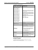
Digital Inputs:
<fb1> through <fb20>
Activates the corresponding LED for as long as the
input is high.
If two buttons are combined, then only the LED for
the top button in the vertical pair will be visible.
High/1 (level sensitive) = Activate LED feedback
Low/0 = Turn off LED
Digital Output:
<FlipTopOpen>
Indicates that the FlipTop cover is fully open. The
feedback remains high for as long as the cover is
open.
If the cover is not fully open the signal will go low,
the keypad buttons will be disabled and the unit
will not report any button presses.
High/1 = FlipTop open
Low/0 = FlipTop not fully open
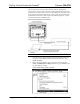
Analog Input:
<Bargraph1>
Sets the levels that will be displayed on the left
bargraph. The bargraph is an 8-segment LED and
is proportional to the input.
Valid values range from 0% to 100%.
Analog Input:
<Bargraph2>
Sets the levels that will be displayed on the right
bargraph. The bargraph is an 8-segment LED and
is proportional to the input.
Valid values range from 0% to 100%.
Example Program
An example program for the C2N-FTB is available from the “Example
Program” section of the Crestron website
(http://www.crestron.com/exampleprograms
). Search for C2N-FTB.ZIP.
22 • FlipTop Control Center with Cresnet
®
: C2N-FTB Operations & Installation Guide - DOC. 6338