Crestron QM-FTDC FlipTop Data Center Operations & Installation Guide
This document was prepared and written by the Technical Documentation department at: Crestron Electronics, Inc. 15 Volvo Drive Rockleigh, NJ 07647 1-888-CRESTRON All brand names, product names and trademarks are the property of their respective owners. ©2005 Crestron Electronics, Inc.
Crestron QM-FTDC FlipTop Data Center Contents FlipTop Data Center: QM-FTDC 1 Introduction ..........................................................................................................1 Features and Functions...........................................................................1 QuickMedia Transport System...............................................................2 Specifications .........................................................................................
Crestron QM-FTDC FlipTop Data Center FlipTop Data Center: QM-FTDC Introduction Features and Functions The QM-FTDC FlipTop Computer Center is part of the Crestron MediaManager™ line of network devices, room control systems and signal routing solutions. It is available in six different models.
FlipTop Data Center Crestron QM-FTDC This Cresnet® device uses QuickMedia™ technology to facilitate an uncomplicated connection of audio, video, and computer equipment. All media and control signals are routed via a single QuickMedia cable for simple installation. A complete integrated room solution is created with the addition of a QuickMedia receiver (such as the QM-RMCRX-BA) and optional keypads or touchpanels. NOTE: The QM-FTDC is compatible with 2-Series control systems only.
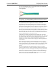
Crestron QM-FTDC FlipTop Data Center The Crestron QuickMedia cable “CresCAT-QM” contains one CAT5E cable and one Cresnet® cable in siamese jackets. CresCAT-QM Cable NOTE: Do not untwist the two wires in a single twisted pair for more than 1/3-1/2" (0.84 – 1.27 cm) when making a connection. The twists are critical to canceling out interference between the wires.
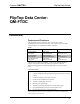
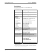
FlipTop Data Center Crestron QM-FTDC Specifications Specifications for the QM-FTDC are given in the following table. QM-FTDC Specifications SPECIFICATION DETAILS Cresnet Power Usage 8 Watts (0.33 Amp @ 24 VDC) Default Network IDs 1A Video Formats RGBHV (VGA), RGsB, YPBPR Video Detection Within 2 seconds Firmware QM-FTDC.V.3.05.upg or later 2-Series Control System Update Files1,2 Version 3.125.
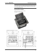
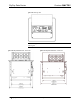
Crestron QM-FTDC FlipTop Data Center NOTE: Crestron software and any files on the website are for Authorized Crestron dealers and Crestron Authorized Independent Programmers (CAIP) only. New users may be required to register to obtain access to certain areas of the site (including the FTP site). Physical Description Refer to the physical views shown below. QM-FTDC - Top Open View QM-FTDC Physical Dimensions – Top View Operations & Installation Guide – DOC.
FlipTop Data Center Crestron QM-FTDC QM-FTDC-NB - Top View NOTE: The physical dimensions of the NB models are identical to the models with keypad. QM-FTDC Physical Dimensions - Front View 6 • FlipTop Data Center: QM-FTDC QMI-FTDC Physical Dimensions - Front View Operations & Installation Guide - DOC.
Crestron QM-FTDC FlipTop Data Center QM-FTDC Bottom View QMI-FTDC Bottom View QM-FTDC Physical Dimensions – Back View QMI-FTDC Physical Dimensions – Back View Operations & Installation Guide – DOC.
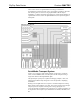
FlipTop Data Center Crestron QM-FTDC QM-FTDC Physical Dimensions – Side View QMI-FTDC Physical Dimensions – Side View Controls and Ports (Top) Buttons The QM-FTDC can have 10 to 20 engravable, replaceable, programmable buttons. All buttons are functionally identical and have light emitting diodes (LEDs) that serve as user feedback indicators. The illumination of each LED (on/off) is independently addressable, and programmable using SIMPL Windows.
Crestron QM-FTDC FlipTop Data Center COMPUTER This female DB15HD connector is used for connecting a computer’s RGB video output to the presentation system. A corresponding 3.5mm mini-jack is provided for the computer sound card output. This port can automatically detect the presence of an H-sync video signal to support RGBHV and RGBS, and component video detection by sensing the green video signal on pin 2 to support RGsB and Y, PB, PR. Refer to the following table for the DB15HD connector pin-assignments.
FlipTop Data Center Crestron QM-FTDC Ethernet One 8-pin RJ-45 port is provided for connection to the Ethernet, providing local area network or Web access (cable is not supplied). Refer to the following table for the Ethernet connector signals and use an appropriate cable.
Crestron QM-FTDC FlipTop Data Center NET (x2) NET 24 Y Z G NET 24 Y Z G These two 4-pin terminal block connectors, located on the bottom side of the QM-FTDC, are for connection to the Cresnet network. One connector is used to connect to the Cresnet network while the second connector can be used to connect another Cresnet device. Cresnet power to the QM-FTDC is supplied through either of these connectors. For more information, refer to “Network Wiring” on page 13.
FlipTop Data Center Crestron QM-FTDC Teleconferencing Ports One 8-pin RJ-45 and two 6-pin RJ-11 communication passthrough ports (labeled 1, 2 and 3) are provided for use with telephone and teleconferencing devices. Bottom labels should match top labels. 1 2 3 Use the label set (included) to change the designations of these ports. AC Power Connect the six-foot (183 cm) grounded AC line cord to supply AC power to the outlet on the topside of the QM-FTDC.
Crestron QM-FTDC FlipTop Data Center Industry Compliance As of the date of manufacture, the QM-FTDC has been tested and found to comply with specifications for CE marking and standards per EMC and Radiocommunications Compliance Labelling. NOTE: This device complies with part 15 of the FCC rules.
FlipTop Data Center Crestron QM-FTDC pin on the network connector, and tin the twisted connection. Apply solder only to the ends of the twisted wires. Avoid tinning too far up the wires or the end becomes brittle. Insert the tinned connection into the Cresnet connector and tighten the retaining screw. Repeat the procedure for the other three conductors. NOTE: For larger networks (i.e.
Crestron QM-FTDC FlipTop Data Center Identity Code Every piece of equipment and user interface within the network requires a unique identity code (Net ID). These codes are two-digit hexadecimal numbers from 03 to FE (Net ID 02 is reserved for master control units). The Net IDs reside within all Cresnet devices (hardware) and must match the Net ID as specified in the software (SIMPL Windows) that runs the system.
FlipTop Data Center Crestron QM-FTDC Network Device Tree 4. Right-click on the device Net ID, and when the sub-menu appears, select Change Network ID from the sub-menu. Network Device Tree – Sub-Menu 5. Enter a new Net ID and press Enter. Enter New Net ID Repeat this procedure for each additional network device requiring a Net ID change. 16 • FlipTop Data Center: QM-FTDC Operations & Installation Guide - DOC.
Crestron QM-FTDC FlipTop Data Center Installation NOTE: This section does not apply to NB models. The QM-FTDC is shipped with ten large blank buttons. You can order a variety of button kits (sold separately) to add as many as 20 engraved or blank buttons.
FlipTop Data Center Crestron QM-FTDC QM-FTCMK Cable Management Plate The QM-FTDC is shipped with a blank bottom plate. A cable management plate is available to provide a pullout cable solution for the computer input and LAN pass-through cables. The kit contains two 6-foot cables (computer and computer audio). • Order the QM-FTCMK Cable Management Kit for domestic models. • Order the QMI-FTCMK Cable Management Kit for international models.
Crestron QM-FTDC FlipTop Data Center Cable Mounting Plate Installation Cable Loops Through the Cable Plate NOTE: Ensure that the cables have sufficient clearance to enable smooth movement. Allow approximately 40 inches (102 cm) from the top surface of the FlipTop box. Mounting to Surface The QM-FTDC is designed to mount in a horizontal surface, such as a desk top, lectern, or podium. The following diagram illustrates the required opening size to accommodate the QM-FTDC.
FlipTop Data Center Crestron QM-FTDC Cutout Dimensions QM-FTDC (4006405) QMI-FTDC (4006874) NOTE: Before inserting the QM-FTDC in the mounting hole, ensure that all required cables have been installed. Mounting Parts Supplied with the QM-FTDC PART DESCRIPTION QUANTITY Screw #6-32, Pan Head, Phillips 8 Screw #10, Pan Head, Phillips 4 Mounting Bracket 2 1. Install the eight supplied #6-32 screws, but do not tighten (four on the front side and four on the rear side).
Crestron QM-FTDC FlipTop Data Center 3. Install the four #10 screws in the mounting brackets (two screws per bracket). Refer to the following diagram. 4. Slide the mounting brackets over the #6-32 screws and tighten the #6-32 screws. 5. Turn the four #10 screws equally until they contact the underside of the mounting surface. NOTE: Do not over-tighten the #10 screws as this may damage the surface and/or the unit.
FlipTop Data Center Crestron QM-FTDC NOTE: The maximum continuous current from equipment under any external load conditions shall not exceed a current limit that is suitable for the minimum wire gauge used in interconnecting cables. The ratings on the connecting unit's supply input should be considered to prevent overloading the wiring. Underside Connections Attach the optional labels (included) to the passthrough telecommunication connectors 1, 2 and 3.
Crestron QM-FTDC FlipTop Data Center Ground Wire Connections NOTE: Do not connect the shield to earth ground at the QM-FTDC. Configuration Software Have a question or comment about Crestron software? Answers to frequently asked questions (FAQs) can be viewed in the Online Help section of the Crestron website. To post a question or view questions you have submitted to Crestron’s True Blue Support, log in at http://support.crestron.com. First-time users will need to establish a user account.
FlipTop Data Center Crestron QM-FTDC • Crestron Engraver version 2.3.3 or later (only required if using SystemBuilder). • Crestron RoomView® version 6.0 (required for room management). NOTE: The NB versions may be programmed with the regular QM FlipTop devices, but will not match during SystemBuilder verification procedure in the finish stage. Configuring with SystemBuilder The easiest method of programming, but does not offer as much flexibility as SIMPL Windows.
Crestron QM-FTDC FlipTop Data Center SystemBuilder – “New” Blank System Option 2. Select the plug-in for a QuickMedia system. SystemBuilder – “Plug-in Selection” Window 3. Select the control processor. NOTE: You can select any 2-Series or QM control processor as the master. Operations & Installation Guide – DOC.
FlipTop Data Center Crestron QM-FTDC SystemBuilder – Select a Control Processor (As the Master) 4. Specify the audio configuration. Choose from the various dialogs (stereo program, speech, etc.) and click Next. Click Finish to continue to the next step. 5. Add RoomView® if desired. 6. Select the device and then click the Assign QuickMedia Devices and located on the menu bar, and drag the Routing button QM devices from the library on the right side, to the QM system on the left side.
Crestron QM-FTDC FlipTop Data Center SystemBuilder – Equipment Room and Library 7. The QM-FTDC has three default programming modules already prepared in SystemBuilder. When you choose the QM-FTDC, the following notice is displayed. Click Yes to select one of the default modules. Default Programming Notice Choosing Yes allows you to select one of the three default programming selections.
FlipTop Data Center Crestron QM-FTDC Default Programming Example – Program and Speech, Dual Volume Control 8. Setup the QM network cable routing. Right-click on the connector and select the routing to the desired device. The connectors that are displayed in the following diagram have an exclamation mark (!) if they are selectable for routing. Routing Example – Right-Click on QM Connector 28 • FlipTop Data Center: QM-FTDC Operations & Installation Guide - DOC.
Crestron QM-FTDC FlipTop Data Center 9. Build the program. The “Finish” window affords an opportunity to set/reset network IDs and verify hardware network IDs. 10. After completing your SystemBuilder program, click the Build and Upload System button . SystemBuilder – “Finish” Window Setting Net IDs in SystemBuilder SystemBuilder provides a convenient method of selecting and assigning Net IDs to devices. 1. Ensure that all network devices are connected to the control system. 2.
FlipTop Data Center Crestron QM-FTDC SystemBuilder – “Finish” Window 3. 30 • FlipTop Data Center: QM-FTDC On the “Finish” window, click the Set Network IDs… button to assign the network IDs. SystemBuilder provides three methods for assigning Net IDs. • Drag and drop a device from the program tree on the left onto the device in the network tree on the right. • Right-click a device the program tree on the left and select Setup from the sub-menu.
Crestron QM-FTDC FlipTop Data Center SystemBuilder – “Set Network IDs” Window Configuring with SIMPL Windows NOTE: While SIMPL Windows can be used to configure the QM-FTDC, Crestron recommends SystemBuilder software for configuring and tuning a QuickMedia system. NOTE: The following are acceptable file extensions for programs that include a QM-RMCRX-BA and QM-FTDC, developed for specific control system types: .smw projectname.smw (source file) .spz projectname.spz (compiled file for 2-Series) .
FlipTop Data Center Crestron QM-FTDC only. New users may be required to register to obtain access to certain areas of the site (including the FTP site). NOTE: The information in this section assumes that the reader has knowledge of SIMPL Windows. If not, refer to the extensive help information provided with the software. NOTE: In the following example, a QM-RMCRX-BA is used as the QuickMedia receiver for the QM-FTDC.
Crestron QM-FTDC FlipTop Data Center QM-FTDC Control Module Within this module are three slots, Basic Controls, Microphone Controls, and Buttons. Drag and drop the QM-FTDC module onto the C2Net-Device slot. This symbol has default Net ID 1A. C2Net-Device, Slot 5 Setting the Net ID in Device Settings Double-click the QM-FTDC icon in the upper pane to open the “Device Settings” window. This window displays QM-FTDC device information.
FlipTop Data Center Crestron QM-FTDC NOTE: This procedure sets the Net ID for the QM-FTDC in the program only. It does not automatically set the Net ID for the QM-FTDC itself. SIMPL Windows automatically changes Net ID values of a device added to a program if a duplicate device or a device with the same Net ID already exists in the program. Always ensure that the hardware and software settings of the Net ID match. For Net ID hardware setting details, refer to “Identity Code” on page 15.
Crestron QM-FTDC FlipTop Data Center QM-FTDC Basic Controls – Signal Descriptions (continued) SIGNAL TYPE AND NAME DESCRIPTION Analog input: Sets the source gain compensation for the COMPUTER AUDIO source. Valid analog values range from -100d (-10dB) to +100d (+10dB), adjustable in increments of 0.1dB (1d = 0.1dB). Analog output: Indicates the source gain compensation being applied to the COMPUTER AUDIO source.
FlipTop Data Center Crestron QM-FTDC The parameters that are associated with QM inputs are stored in the transmitter. Input compensation and Mic EQ are examples of this. This information is then transmitted along with the digital audio. The DSP that does the compensation and EQ are in the receiver, but the settings now travel with the audio signal.
Crestron QM-FTDC FlipTop Data Center QM-FTDC Microphone Control – Signal Descriptions (continued) SIGNAL TYPE AND NAME DESCRIPTION Digital output: Indicates that phantom power has been enabled. High/1 = Phantom power is on; Low/0 = Phantom power is off Analog inputs: Sets the threshold for gating. The noise gate is enabled for as long as the input is high. Valid gating values range from 0% to 100%.
FlipTop Data Center Crestron QM-FTDC QM-FTDC Microphone Control – Signal Descriptions (continued) SIGNAL TYPE AND NAME DESCRIPTION Analog outputs: through Indicates the trim being applied to each band of the MIC 1 equalizer. Analog inputs: through Sets the four MIC 1 EQ trims (at 160Hz, 500Hz, 1.2kHz, and 3kHz). Valid analog values range from -120d (-12dB) to +120d (+12dB), adjustable in increments of 0.1dB (1d = 0.1dB).
Crestron QM-FTDC FlipTop Data Center combined. No other combinations are valid. That is, two buttons cannot be combined horizontally; the buttons on rows 2 and 3 cannot be combined.
FlipTop Data Center Crestron QM-FTDC QM-FTDC Buttons – Signal Descriptions (continued) SIGNAL TYPE AND NAME DESCRIPTION Digital output: Indicates that the FlipTop cover is fully open. The feedback remains high for as long as the cover is open. If the cover is not fully open the signal will go low, the keypad buttons will be disabled and the unit will not report any button presses.
Crestron QM-FTDC FlipTop Data Center Gain An adjustable amplification to accommodate varying input signal levels. Gating Gating is a function that mutes a microphone signal when the input sound level is below a user-set threshold (gating level). The following diagram demonstrates clipping, attack time, decay time, and gating level.
FlipTop Data Center Crestron QM-FTDC Setting Microphone Gain The QM-FTDC provides variable gain on the microphone inputs. The following procedure is used to set the optimal gain for a microphone input. Use the Realtime Mode in SystemBuilder to control phantom power, gain and gate settings, and to monitor the gate, normal, and clip level indicators. For information on using SystemBuilder software, refer to the extensive help information provided with the software.
Crestron QM-FTDC FlipTop Data Center NOTE: The “attack” and “decay times” are applied to both microphone inputs. 5. Set the system output volume to a desirable listening level. While providing realistic voice input and background noise levels, adjust the gating level and attack/decay times to eliminate undesired input while providing the best content quality.
FlipTop Data Center Crestron QM-FTDC The following serial connection is unique to the QM-RMCRX-BA. Null Modem Cable Pins Pins 2 2 3 3 5 5 7 7 8 8 Connect the COM B port on the QM-RMCRX-BA control system to one of the COM ports (usually COM 1) on the PC. The QM-RMCRX-BA requires the use of a null-modem RS-232 cable with DB9 female connectors on both ends.
Crestron QM-FTDC FlipTop Data Center Crestron Toolbox – “Address Book” Window The PC communication settings specified in the address book should match the protocol that the QM-RMCRX-BA expects. The settings are as follows: • Port = COM 1 through COM 8. Select the correct COM port on the PC. • Baud rate = Auto Detect. • Parity = None. • Number of data bits = 8. • Number of stop bits = 1. • Hardware handshaking (RTS/CTS) enabled. • Software handshaking (XON/XOFF) not enabled. 2.
FlipTop Data Center Crestron QM-FTDC “System” Info Window NOTE: To enter the console mode, click the console mode icon . Uploading a SIMPL Windows Program A control system source file has the extension .smw. A compiled SIMPL Windows file has the extension .spz for a 2-Series control system. The SIMPL Windows file can be uploaded to the control system using SIMPL Windows or via the Crestron Toolbox. Upload via SIMPL Windows 1. Start SIMPL Windows. 2.
Crestron QM-FTDC FlipTop Data Center Crestron Toolbox– Tools | System Info 3. Select Functions | SIMPL Program… Functions Menu – SIMPL Program Selection NOTE: The available functions depend on the type of device. The “SIMPL Program” window permits you to browse for a compiled program file (.spz), and allows you to upload to internal flash or compact flash. Operations & Installation Guide – DOC.
FlipTop Data Center Crestron QM-FTDC “SIMPL Program” Window 4. Browse for the appropriate .spz file in the “Open” window, and click Open. “Open” Window 5. When the “SIMPL Program” window reappears, click Send. 6. To verify that the program has been transferred successfully, select Functions | SIMPL Program. Details about the current program loaded in the control system are displayed in the upper left corner of the “SIMPL Program” window. Firmware Upgrade A firmware upgrade file has the extension .
Crestron QM-FTDC FlipTop Data Center To upgrade the firmware, complete the following steps. NOTE: A firmware upgrade file has the extension .upg. The following is the acceptable file extension for a firmware update file. .upg QM-FTDC.V.XXXXX.upg 1. Make sure that “Communication Settings,” which begins on page 43, has been performed. 2. Open Crestron Toolbox. 3. Once communication is established, click Tools | System Info. The Functions menu becomes available. 4.
FlipTop Data Center Crestron QM-FTDC 6. The Open window allows you to browse to the desired filename (.upg) file. Click Open to begin the transfer. “Open” Window 7. The “Firmware” window reopens and indicates the new firmware version. NOTE: If problems arise when transferring any Cresnet file (touchpanel project/firmware), lower the port speed baud rate to 38400 to match the Cresnet bus speed. Problem Solving The following table provides corrective action for possible trouble situations.
Crestron QM-FTDC FlipTop Data Center QM-FTDC Troubleshooting (continued) TROUBLE POSSIBLE CAUSE(S) CORRECTIVE ACTION Video from RGB source is garbled or no output. Incorrect cable connections. Verify 15-pin output cable connection. Verify QM input cable connections. Signal skew due to cable length or unequal pair length. Verify maximum QM cable length and compensation for skew. Poor RGB or video image quality.
FlipTop Data Center Crestron QM-FTDC Further Inquiries If you cannot locate specific information or have questions after reviewing this guide, please take advantage of Crestron's award winning customer service team by calling the Crestron corporate headquarters at 1-888-CRESTRON [1-888-273-7876]. For assistance in your local time zone, refer to the Crestron website (www.crestron.com) for a listing of Crestron worldwide offices.
Crestron QM-FTDC FlipTop Data Center Appendix A: International Receptacles PART NUMBER DESCRIPTION COUNTRIES 6003287 PWR-AU-B POWER RECEPTACLE, AUSTRALIA, 250V, 10A, BLK Australia, Fiji, New Zealand, Papua New Guinea 6003288 PWR-EU-B POWER RECEPTACLE, EUROPEAN "SCHUKO", 250V, 16A, BLK Austria, Azerbaijan, Belarus, Bosnia and Herzegovina, Brunei, Bulgaria, Burundi, Cape Verde, Chad, Croatia, Czech Republic, Egypt, Eritrea, Finland, Georgia, Germany, Greece, Greenland, Guinea-Bissau, Hungary, Icelan
FlipTop Data Center Crestron QM-FTDC Appendix B: QuickMedia Installation and Compensation Installation Notes You must pass audio through from transmitters to receivers even if you are not using the audio signal. The information required for auto-compensation is transmitted along with the audio. In addition, the QM Link signal indicates that the QM cable is connected and that an audio signal is present on the cable.
Crestron QM-FTDC FlipTop Data Center Auto Compensation with a Self-Peaking Receiver Crestron's innovative self-peaking audio circuit eliminates the need to peak the audio signal. Without self-peaking the same peak and boost values are applied equally to the video and audio signals. When these signals travel the same path, this arrangement is satisfactory. However, when video and audio travel to a receiver from different paths, unequal cable lengths are created.
FlipTop Data Center Crestron QM-FTDC Compatibility Charts Under certain circumstances, the audio and video may be acceptably peaked even though the audio and video path lengths are different. Because the audio signal is digital, and more forgiving than the video signal, it may be possible to peak the video and have functioning audio. It is difficult to predict outcomes because it is dependent on the difference in cable lengths, the video rates, and acceptable video quality.
Crestron QM-FTDC FlipTop Data Center KEY: 9 = Good operation. 1. = Operation depends on video rates and if the audio and video cable lengths are closely matched. 2. = In these cases, if the audio and video (although from different sources), switch together consistently, the system will operate normally. If the audio and video switch inconsistently, operation then depends on the video rates and how closely the audio and video cable lengths match. * = Device with self-peaking.
FlipTop Data Center Crestron QM-FTDC Return and Warranty Policies Merchandise Returns / Repair Service 1. No merchandise may be returned for credit, exchange, or service without prior authorization from CRESTRON. To obtain warranty service for CRESTRON products, contact the factory and request an RMA (Return Merchandise Authorization) number. Enclose a note specifying the nature of the problem, name and phone number of contact person, RMA number, and return address. 2.
Crestron QM-FTDC FlipTop Data Center This page intentionally left blank. Operations & Installation Guide – DOC.
Crestron Electronics, Inc. 15 Volvo Drive Rockleigh, NJ 07647 Tel: 888.CRESTRON Fax: 201.767.7576 www.crestron.com Operations & Installation Guide – DOC. 6312A (2011599) 08.05 Specifications subject to change without notice.