
User Guide

FlipTop Data Center Crestron QM-FTDC
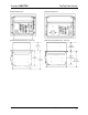
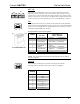
Ethernet
8
1
One 8-pin RJ-45 port is provided for connection to the Ethernet, providing
local area network or Web access (cable is not supplied). Refer to the
following table for the Ethernet connector signals and use an appropriate cable.
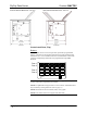
E
thernet Connector Pinou
t
PIN SIGNALS
1 TX + passthrough
2 TX - passthrough
3 RC+ passthrough
4 passthrough
5 passthrough
6 RC - passthrough
7 passthrough
8 passthrough
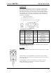
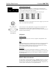
Teleconferencing Ports
123
One 8-pin RJ-45 and two 6-pin RJ-11 communication passthrough ports
(labeled 1, 2 and 3 respectively) are provided for use with telephone and
teleconferencing devices.
Use the label set (included) to change the designations of these ports.
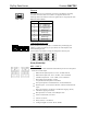
Ports (Underside)
MIC 1 / MIC 2
These two 5-pin 3.5 mm detachable terminal blocks provide two microphone
and line level audio inputs.
• Balanced microphone input level: -60 to –20 dBV nominal
• Balanced line input level: -28 to +12 dBV, 4 V
RMS
maximum
• Unbalanced input level: -34 to +6 dBV, 2 V
RMS
maximum
• Microphone input impedance: 10 kΩ,
accepts balanced microphones 60 to 600 Ω
• Line input impedance: 22 kΩ (balanced), 11 kΩ (unbalanced)
• Phantom power: 10 mA (total) at 48 VDC, software enabled for both
inputs
• Mic level indicators (via software): 20 dB below clipping (Norm),
6 dB below clipping (Overload)
• Mic Input Gain: 0 to 100% (0 to 40 dB) plus mute
• Gate level (threshold): 0 to 100%
• Attack: 1 to 100 ms
• Decay (release): 1 to 5000 ms
• Analog to Digital conversion: 24-bit, 48 kHz
10 • FlipTop Data Center: QM-FTDC Operations & Installation Guide - DOC. 6312A