
User Guide

Crestron QM-FTDC FlipTop Data Center
NET (x2)
NET
24 Y Z G
NET
24 Y Z G
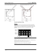
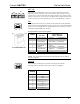
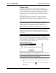
These two 4-pin terminal block connectors, located on the bottom side of the
QM-FTDC, are for connection to the Cresnet network. One connector is used to
connect to the Cresnet network while the second connector can be used to connect
another Cresnet device. Cresnet power to the QM-FTDC is supplied through either
of these connectors. For more information, refer to “Network Wiring” on page 13.
QM
8
1
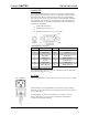
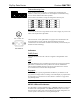
This eight-pin RJ-45 transport port, located on the bottom side of the QM-FTDC,
allows connection of the QuickMedia cable. It carries audio, video, and microphone
signals over CresCAT-QM cable to a QuickMedia receiver or switcher. For more
information on QuickMedia refer to page 2.
RJ-45 QuickMedia Connector Pin Assignments
RJ-45 PIN
NUMBER
WIRE COLORS
(EIA 568B)
QM ASSIGNMENT
RGB, COMPOSITE,
S-VIDEO, AND AUDIO
1 WHITE/ORANGE - RGB RED (- CHROMINANCE)
2 ORANGE + RGB RED (+ CHROMINANCE)
3 WHITE/GREEN - RGB GREEN (- LUMINANCE)
4 BLUE + AUDIO
5 WHITE/BLUE - AUDIO
6 GREEN + RGB GREEN (+ LUMINANCE)
7 WHITE/BROWN - RGB BLUE (- COMPOSITE)
RJ-45 MALE CONNECTOR
8 BROWN + RGB BLUE (+ COMPOSITE)
NOTE: Always use Crescat-QM cable to make QuickMedia connections.
NOTE: Crescat-QM siamese cable includes four additional wires for making
Cresnet connections.
Ethernet
8
1
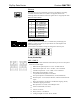
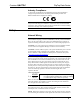
One 8-pin RJ-45 passthrough port used for connection to the Ethernet,
providing local area network or Web access (cable is not supplied).
RJ-45 PIN
NUMBER
SIGNALS
1 TD +
2 TD -
3 RD +
4 Connected to pin 5
5 Connected to pin 4
6 RD -
7 Connected to pin 8
8 Connected to pin 7
Operations & Installation Guide – DOC. 6312A FlipTop Data Center: QM-FTDC • 11