Crestron MMK-12L & WMKM-12L Mud Mount Kits Installation Guide
This document was prepared and written by the Technical Documentation department at: Crestron Electronics, Inc. 15 Volvo Drive Rockleigh, NJ 07647 1-888-CRESTRON All brand names, product names and trademarks are the property of their respective owners. ©2005 Crestron Electronics, Inc.
Crestron MMK-12L & WMKM-12L Mud Mount Kits Mud Mount Kits: MMK-12L & WMKM-12L Description Mud Mount Kits are the preferred mounting option for the Crestron Isys® TPS-12L and TPS-12G-L series of wall mounted touchpanels when cutouts made in the drywall for touchpanel installation are too large. These kits provide support for additional plastering that can be applied to hide large irregularities in the touchpanel cutout.
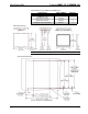
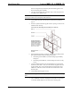
Mud Mount Kits Crestron MMK-12L & WMKM-12L Supplied Hardware of the MMK-12L and WMKM-12L DESCRIPTION PART NUMBER QUANTITY Metal Plate, Mounting (WMKM-12L only) Metal Plate, Mud Ring Metal Plate, Fastener Hardware, Push-On Fastener 2012963 1 2013002 2004825 2004121 1 2 4 Dimensional Drawings NOTE: You can use the mounting plate as a cutout template. Drywall Cutout Dimensions 2 • Mud Mount Kits: MMK-12L & WMKM-12L Installation Guide – DOC.
Crestron MMK-12L & WMKM-12L Mud Mount Kits Installation This section provides an installation procedure for each Mud Mount Kit. The procedure for the MMK-12L starts below and the “WMKM-12L Procedure” starts on page 5. MMK-12L Procedure The procedure in this section provides the necessary steps for the assembly of the MMK-12L to either the PMK-12L or BB-12L.
Mud Mount Kits Crestron MMK-12L & WMKM-12L them on enough to keep the fastener plate and mounting plate as one fastener/mounting plate assembly. 3. Use the second fastener plate and repeat steps 1 and 2 using the lower two PMK-12L (or BB-12L) pins. NOTE: When installing into the PMK-12L, verify that the 18 AWG bus wire securing the cables for the touchpanel remain attached. 4. Verify that the drywall cutout meets the measurements specified on page 2. 5.
Crestron MMK-12L & WMKM-12L Mud Mount Kits 10. Apply drywall joint compound as needed to finish the cutout. Avoid covering the four tapped mounting holes. 11. Run the necessary cables for the touchpanel and secure them behind the drywall. 12. When dry, the touchpanel can be installed using the four tapped holes in the PMK-12L. Refer to the latest revision of the TPS-12L/15L/17L Operations Guide (Doc. 6355) or TPS-12G/15G-L Operations Guide (Doc. 6356) for installation instructions.
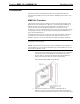
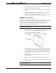
Mud Mount Kits Crestron MMK-12L & WMKM-12L 6. Use the drywall saw or equivalent to produce a level, rectangular cutout in the drywall as shown on page 2. 7. Insert the symmetrical mud ring plate into the opening, as shown in the illustration after this step. Insert the Mud Ring Plate into the Opening 8. Carefully pass the fastener/mounting plate assembly through the opening and rest the assembly against the interior surface of the drywall.
Crestron MMK-12L & WMKM-12L Mud Mount Kits the clearance holes in the plate and are secured in the extruded holes of the fastener plates. 11. Verify that the plate is level before tightening. NOTE: Do not over tighten screws. Doing so may over-dimple or rip the plate. 12. Use a #2 Phillips screwdriver and tighten the drywall screws by hand so that they slightly dimple into the holes in the mud ring plate. 13. Run the necessary cables for the touchpanel and secure them behind the drywall. 14.
Mud Mount Kits Crestron MMK-12L & WMKM-12L Return and Warranty Policies Merchandise Returns / Repair Service 1. No merchandise may be returned for credit, exchange, or service without prior authorization from CRESTRON. To obtain warranty service for CRESTRON products, contact the factory and request an RMA (Return Merchandise Authorization) number. Enclose a note specifying the nature of the problem, name and phone number of contact person, RMA number, and return address. 2.
Crestron MMK-12L & WMKM-12L Mud Mount Kits This page intentionally left blank. Installation Guide – DOC.
Crestron Electronics, Inc. 15 Volvo Drive Rockleigh, NJ 07647 Tel: 888.CRESTRON Fax: 201.767.7576 www.crestron.com Installation Guide – DOC. 6359 (2013442) 07.05 Specifications subject to change without notice.