
User Guide

Software Crestron Serial Mouse Control Driver
Cabling Connections
For Serial Mouse Control Driver operation using Ethernet communication with the PC, refer
to the steps below.
1. Refer to the appropriate (for TPS-XVGA, TPS-XVGA-BV, or TPS-XVGAL
card) diagrams and tables on the next two pages and make the cable connections.
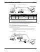
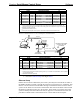
Ethernet Communication #1 - Tilt Touchpanel with TPS-XVGA
TO
RGB
PORT
RGB CABLE
PC
LAN
PORT
ETHERNET
WIRING
COM
PORT
CONTROL
SYSTEM
ETHERNET
ROUTER/HUB
COM
PORT
TILT TOUCHPANEL
WITH TPS-XVGA
VGA
PORT
A
COMM. CABLE
B
D
C
LAN
PORT
POWER
PACK
E
24VDC
2.0A
PORT
BKLT
MENU
PROFESSIONAL CONTROL PROCESSOR
PRO
2
CRESTRON
PORT CONNECTOR to CONNECTOR DEVICE PORT
A
1
VGA DB-15, male DB-15, male Touchpanel RGB
B
2
COM DB-9, female DB-9, female Control System COM
C
3
LAN RJ-45, 8-pin RJ-45, 8-pin Ethernet / Hub na
D
3
na RJ-45, 8-pin RJ-45, 8-pin Touchpanel LAN
E
4
na na Touchpanel 24VDC 2A
1
2
3
4
REF
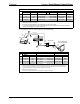
ETHERNET COMMUNICATION #1 - TILT TOUCHPANEL WITH TPS-XVGA CARD
CABLING REQUIRED TO
Control System
DEVICE
PC
Standard Ethernet cables (ref C & D).
Standard stranded VGA monitor cable.
PC
Standard null modem serial cable.
FROM
Ethernet / Hub
PWR. PACK
Power pack is NOT required if control system is connected to touchpanel via Ethernet AND Cresnet.
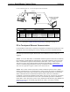
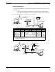
Ethernet Communication #2 - Tilt Touchpanel with TPS-XVGA-BV
RGB CABLE
PC
TILT TOUCHPANEL
WITH TPS-XVGA-BV
COM
PORT
CONTROL
SYSTEM
RGB
PORT
RGB
PORT
TPS-IMC-BV
AUDIOVIDEO
NET/
TO PANEL
RGB
BAL
INPUT
AUDIO
INPUT
AUDIO
+
R
S +- -
L
S
COAX
MIC
OUT
-+ S
NTSC/PAL VIDEO
NET
Z G
24VDC
Y242.0A
VIDEO
BALANCED
RGB Y
COMP
C
CRESTRON
TPS-IMC-BV
ETHERNET
WIRING
ETHERNET
ROUTER/HUB
LAN
PORT
COMM. CABLE
COM
PORT
VGA
PORT
LAN
PORT
A
C
B
E
D
24VDC
2.0A
PORT
POWER
PACK
F
NET/
VIDEO
PORT
RGB
PORT
G
TO
NET/
VIDEO
PORT
BKLT
MENU
PROFESSIONAL CONTROL PROCESSOR
PRO
2
CRESTRON
10 • Serial Mouse Control Driver Programmer’s Guide - DOC. 5916A