
User Guide

Crestron Serial Mouse Control Driver Software
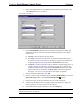
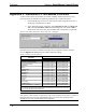
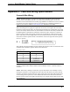
5. Refer to the diagram below. In the Type drop-down list of the desired Pad Area,
select Mouse (Pad Area 1 is shown).
Select Mouse in Pad Area 1
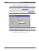
6. In the Communication via drop-down list of the Project Properties dialog box,
select either Serial or Cresnet or TCP/IP (for Ethernet operation) and continue
with this step.
6a. If Serial is selected, proceed to step 7 below.
6b. If Cresnet is selected, select the serial join number (specified during step 1
of “SIMPL Windows Programming” that begins on page 13) to reference the
assigned touchpanel serial output from the Serial Join drop-down list.
6c. If TCP/IP is selected, select the serial join number (specified during step 1 of
“SIMPL Windows Programming” that begins on page 13) to reference the
assigned touchpanel serial output from the Serial Join drop-down list. Then
select the desired device ID from the Device ID drop-down list (specified
during step 3 of “VT Pro-e Programming” that begins on page 16.)
7. In Project Properties dialog box, click OK.
8. Open (or create) a page or subpage and select Draw | RGB Window (or from the
Objects Drawing toolbar, click the Draw RGB Window
button).
9. Position the cursor on the page and drag out a box of the desired size.
10. Double-click the RGB window to display “RGB Video Properties” dialog box
and set parameters, as with any other VT Pro-e object.
11. In the RGB Video Properties dialog box, select the Design tab.
NOTE: Full screen RGB video is recommended. If full screen RGB video is not used,
calibration of the screen is required.
Programmer’s Guide - DOC. 5916A Serial Mouse Control Driver • 17