
Specifications


PROCISE 7.3 Surround Sound Processor Crestron PSPHD
20 • PROCISE 7.3 Surround Sound Processor: PSPHD Operations Guide – DOC. 6837C
Connectors, Controls & Indicators (Continued)
# CONNECTORS*,
CONTROLS &
INDICATORS
DESCRIPTION
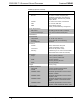
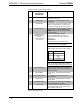
6 SETUP Button (1) push button, enters the compression and
equalization setup menu
7 INFO Button (1) push button, enables display of source
information
8 HOME Button (1) push button, returns both displays to their
default screens showing the current source
and decoding mode (left) and volume (right)
9 DISPLAY Button (1) push button, normally sets the front panel
display brightness; pressing DISPLAY and
HOME simultaneously for 5 seconds enters
the Installer menu
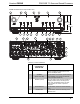
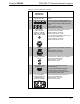
10 MICROPHONE,
RESET Button, and
USB Port
(behind removable
front panel)
(1) 3-pin mini-XLR jack, female:
Input for calibrated microphone (part of
CSSTK Surround Sound Tuning Kit, sold
separately)
RESET Button:
Miniature push button, hardware reset.
NOTE: Be sure that any connected amplifier
is turned off before pressing RESET.
(1) USB Type B female:
USB computer console port (cable included)
PIN DESCRIPTION
1
+5 VDC
2 Data -
3
Data +
4
Ground
NOTE: To prevent damage to the PSPHD’s
finish, use a flat-edge tool made of plastic or
covered in tape when removing the front panel
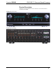
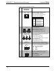
11 DISPLAY (RIGHT) 256 x 64 graphic VFD (Vacuum Fluorescent
Display); Shows volume level, VU meter, and
spectrum analyzer
12 METER Button (1) push button, enables dual analog meter
display
13 SPECTRUM Button (1) push button, enables dual spectrum
analyzer display
14 LEVEL Button (1) push button, enables display of speaker
volume levels
15 AMPLIFIER Button (1) push button, enables display of amplifier
status (if PROAMP is connected)
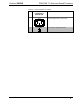
16 Volume Knob (1) rotary encoder with integral push button,
turn to adjust master volume level, press to
display master volume level
(Continued on following page)