Crestron 2-Series Control Systems Reference Guide
This document was prepared and written by the Technical Documentation department at: Crestron Electronics, Inc. 15 Volvo Drive Rockleigh, NJ 07647 1-888-CRESTRON All brand names, product names and trademarks are the property of their respective owners. ©2006 Crestron Electronics, Inc.
Crestron 2-Series Control Systems Reference Guide Contents 2-Series Control Systems 1 Introduction ............................................................................................................................... 1 Programming Tools & Utilities ................................................................................................. 3 SIMPL Windows......................................................................................................... 3 VisionTools Pro-e ..........
Crestron 2-Series Control Systems Reference Guide Crestron Toolbox....................................................................................................... 54 SIMPL Windows....................................................................................................... 56 Web Page Basics ....................................................................................................... 56 Compiling and Uploading a Program ............................................................
Crestron 2-Series Control Systems Reference Guide 2-Series Control Systems Introduction Crestron® control systems are at the center of every Crestron facility control system. The 2-Series line of control systems share commonality across the product line and offer a variety of development tools and techniques previously unavailable in previous Crestron control systems. Crestron 2-Series control systems include the AV2 and PRO2.
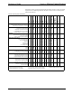
Reference Guide Crestron 2-Series Control System Each of the 2-Series control systems has unique features to meet a variety of system requirements. The following table lists all of the Crestron 2-Series control systems and their key features.
Crestron 2-Series Control Systems Reference Guide Programming Tools & Utilities Many of the activities discussed in this document require the use of Crestron’s suite of programming tools and utilities. They include: • SIMPL™ Windows® • VisionTools® Pro-e • Crestron Toolbox • Test Manager • Viewport (limited use) The latest versions can be obtained from the Crestron website (www.crestron.com/updates).
Reference Guide Crestron 2-Series Control System • Run scripts to automate tasks. • Perform system diagnostics, and much more. Crestron Toolbox allows you to perform these functions using simple graphical views and click and drag methods. Crestron Toolbox also contains the Network Analyzer and Test Manager (expected 2Q 2006) utilities.
Crestron 2-Series Control Systems Reference Guide Establishing Communications with the Control System Whether uploading programs, troubleshooting, or performing diagnostics communication between the control system and a PC must be established. In electronic terms, a “console” provides a means of communication between an operator and the central processing unit of a computer. Crestron Toolbox lets you talk to the console of a 2-Series dual bus control system.
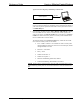
Reference Guide Crestron 2-Series Control System Typical Connection Diagram for Establishing Communication Control System RS-232 NOTE: Certain control systems do not have a COMPUTER port and require an alternate method for establishing serial communications. Refer to your control system’s Operations Guide if the control system does not have a COMPUTER port. 2. Open Crestron Toolbox and click Tools | Manage Address Book to display a list of available devices.
Crestron 2-Series Control Systems Reference Guide “Address Book” Window – Serial Setup Reference Guide – DOC. 6256A 3. After setting the correct parameters, click OK to return to the Crestron Toolbox main window. 4. icon to display the control system information. Select the Click the entry for the control system or Serial on COM1 from the drop down list (located on the bottom of the screen) if it is not already selected.
Reference Guide Crestron 2-Series Control System “System Info” Window for PRO2 Once the system information is displayed a variety of functions are available to the user. For more information, refer to the Crestron Toolbox help file. 8 • 2-Series Control Systems Reference Guide – DOC.
Crestron 2-Series Control Systems Reference Guide NOTE: Crestron Toolbox displays a customized list of functions depending on the type of device with which it is communicating. TCP/IP Connection Before communicating with an Ethernet-enabled control system over TCP/IP, a static IP address or the address/host name of the DHCP server (if DHCP is to be used) must be obtained from the network administrator. The RS-232 connection previously described must be used to configure the unit’s TCP/IP settings.
Reference Guide Crestron 2-Series Control System The IP addresses of LAN A and LAN B cannot be the same. iii. Enter the hostname in the Host Name field. The host name identifies the control system on the network and is automatically translated into the numerical IP address. The host name can consist of up to 64 characters. Valid characters are 0 – 9, A – Z (not case-sensitive), and the dash (hyphen character). No other characters are valid. The host name cannot begin with a dash or number.
Crestron 2-Series Control Systems Reference Guide figure illustrates pinouts for straight through and crossover RJ-45 cables. Pins 4, 5, 7, and 8 are not used. RJ-45 Pinouts 4. Open the address book in Crestron Toolbox by selecting Tools | Manage Address Book or clicking . 5. Create a new entry for the control system by clicking Add Entry or pressing F3. 6. Enter a name for the control system connection and select TCP as the connection type. “Address Book” Window - Entering New TCP-IP Entry 7.
Reference Guide Crestron 2-Series Control System NOTE: This procedure requires the use of the Crestron Viewport. For detailed instructions and information, refer to “Appendix A: Interfacing a Control System with a Modem” on page 82. Passthrough Mode (Viewport Only) Viewport can be used to communicate with devices that are attached to a control system’s serial port. For more information, refer to “Appendix B: Passthrough Mode” on page 89. 12 • 2-Series Control Systems Reference Guide – DOC.
Crestron 2-Series Control Systems Reference Guide Troubleshooting Communications Use the following checklist if communication cannot be established with the control system. 1. If possible remove any cards that are in the card cage, Cresnet devices and the Ethernet card (if applicable). 2. Verify that you are using the correct cables. As described previously, most RS-232 connections between a control system and a PC require a straightthrough serial cable.
Reference Guide Crestron 2-Series Control System Crestron Toolbox Message (PRO2 Shown) c. d. Release the SW-R button. If communication still cannot be established or the console is displaying a prompt: - Remove power from the control system. - Press and hold the SW-R button on the front panel of the control system. - Reapply power to the control system while still holding the SW-R button. - The console should display the message previously shown. - Release the SW-R button.
Crestron 2-Series Control Systems Reference Guide • Number of data bits = 8. • Number of stop bits = 1. • Hardware handshaking (RTS/CTS) enabled. • Software handshaking (XON/XOFF) not enabled. 4. Power down the control system. 5. In Crestron Toolbox, open a text console to the new address book entry. 6.
Reference Guide Crestron 2-Series Control System 2-Series Console Commands Introduction The 2-Series processor is capable of understanding and responding to a set of recognizable words known as console commands. The processor, in essence, is a computer capable of interpreting commands received by the console via different methods.
Crestron 2-Series Control Systems Reference Guide “SIMPL Windows Preferences” Window After enabling viewing of special symbols, the Console symbol can be viewed as shown in the following diagram.
Reference Guide Crestron 2-Series Control System “SIMPL Windows Preferences” Window After enabling viewing of special symbols, the Console symbol can be viewed as shown in the following diagram. The User Program Commands Symbol in SIMPL Windows The User Program Commands symbol receives data entered at the 2-Series console prompt using the USERPROGCMD command. The syntax of the console command requires double-quotes before and after the command string. The string may include escape codes such as "\x".
Crestron 2-Series Control Systems Reference Guide Commands are case insensitive and can be entered from the appropriate prompt (i.e., AV2, PRO2, DVP4DI, etc.). Help on individual commands is available by typing the command followed by a "?" (i.e., ADDMASTER ?). The following table lists acceptable commands alphabetically and provides a brief description of each command. Refer to “Appendix C: Console Command Listing” on page 91 for detailed information.
Reference Guide Crestron 2-Series Control System List of Acceptable Commands for the 2-Series Dual Bus Control System (Continued) COMMAND HOSTNAME I2CERROR ICMP INFO INITIALIZE INPUT IPADDRESS IPMASK IPTABLE ISDIR KILLSOCKET LISTDNS MAKEDIR MESSAGE MODEMINITSTRING NATENABLE NATREMOTE DESCRIPTION Set the host name to be used in a DNS/DHCP environment Enable reporting of I2C errors Enable/disable response to ICMP ping requests Print software capabilities Clear internal file system Set the DVP4 input resolu
Crestron 2-Series Control Systems Reference Guide List of Acceptable Commands for the 2-Series Dual Bus Control System (Continued) COMMAND SHOWEXTRAERRORS SHOWHW SHOWPORTMAP SSL STANDBY STBYTO SYSTEM TELNETPORT TESTDNS TIMEDATE TOUCH TYPE UPLOAD UPTIME USERPROGCMD USERPASSWORD VERSION WEBINIT WEBPORT WEBSERVER WHO XGETFILE XONXOFF XPUTFILE DESCRIPTION Enables extended error reporting Display hardware configuration Display the portmap from the NAT table Configure the SSL options Put the DVP4 into standby
Reference Guide Crestron 2-Series Control System Command Structure Details about each of the acceptable commands that can be interpreted by the 2-Series Dual Bus Control System can be found in “Appendix C: Console Command Listing” on page 91. Commands are listed alphabetically.
Crestron 2-Series Control Systems Reference Guide 2-Series Memory & Directory Structure Introduction A 2-Series control system has 36MB of built-in memory (non-volatile and volatile). The following diagram illustrates the memory structure of the 2-Series Control System. 2-Series Memory Structure 32 MB SDRAM Volatile Memory 256 kB NVRAM 1.5 MB of operational memory (CUZ file) 2.5.
Reference Guide Crestron 2-Series Control System The 4MB flash memory consists of approximately 1.5MB used for firmware (.cuz file), and approximately 2.5MB available for the SIMPL program and SIMPL+ modules. The files that reside in flash conform to a flat directory structure. The following table presents the structure of the overall file system. The directory structure of the 2-series control system can be broken down into two parts.
Crestron 2-Series Control Systems 2. Reference Guide Signals explicitly written to NVRAM (by symbols such as Analog RAM, Analog RAM from database, Serial RAM, Serial RAM from database, Analog Non-volatile Ramp, Digital RAM, etc.) Volatile (SDRAM) 1. Digital, analog and serial signal values 2. SIMPL+ Variables (if "volatile" qualifier is used, or #DEFAULT_VOLATILE is used) DRAM is used by the operating system for dynamic storage of variables, signals and other constructs used at runtime.
Reference Guide Crestron 2-Series Control System To set up an NVRAM disk, perform the following. 1. Open Crestron Toolbox and establish communications with the control system as described on page 5. 2. Select Functions | NVRAM Disk… to open the “NVRAM Disk” window. “NVRAM Disk” Window 3. Enable the NVRAM Disk by selecting Enable NVRAM Disk. 4. Select the size of the NVRAM Disk. 5. Click OK or Apply to create the NVRAM Disk.
Crestron 2-Series Control Systems Reference Guide “Program NVRAM” Window 3. Click the Browse button next to the Retrieve button and specify the name and location of the file to be saved. 4. Click Retrieve. A status bar will display the progress of the file transfer. Restoring NVRAM Files to the Control System NVRAM files can be restored to the control system from a saved file. To restore NVRAM data to the control system from a saved file: 1.
Reference Guide Crestron 2-Series Control System 2. Open a text console window and type NVRAMREBOOT ON. This command will write messages created during rebooting to NVRAM. If an anomaly exists, this command will save the error even though the control system has rebooted. 3. To view the contents of NVRAM, retrieve the file from NVRAM as described in “Retrieving NVRAM Files from the NVRAM Disk” on page 26 and open the error log as described in “Viewing Error Messages with Crestron Toolbox” on page 30.
Crestron 2-Series Control Systems Reference Guide 2-Series Control System Error Messages Introduction This section provides a brief description of 2-Series error messages that one may encounter. Error messages may be the result of hardware or software failure, hardware incompatibility with software definitions, or a programming error. An error is indicated by the MSG / ERR LED on the front panel of the control system.
Reference Guide Crestron 2-Series Control System Viewing Error Messages with Crestron Toolbox Crestron Toolbox can be used with any 2-Series control system to view messages stored in the error log. To manage the Error Log with Crestron Toolbox: 1. Open Crestron Toolbox and establish communications with the control system as described on page 5. 2. Select Functions | Error Log to open the “Error Log” window.
Crestron 2-Series Control Systems Reference Guide Error Levels The following table lists and defines the four levels of error messages that may appear. Error Message Levels TYPE DEFINITION Notice An event has occurred that is noteworthy, but will not affect program operation. The MSG/ERR LED on the front panel does not illuminate when Notice-level errors occur. Warning An event has occurred that could affect program operation, but the program can still run normally.
Reference Guide Crestron 2-Series Control System Master-Slave Modes Introduction Master-Slave mode is a network configuration that allows a Crestron 2-Series control system to access ports on other Crestron 2-Series control systems over Cresnet or Ethernet. By attaching a “slave” control system to a “master” control system, the master control system can use ports it may not normally have (I/O, IR, RF, etc.).
Crestron 2-Series Control Systems Reference Guide Control systems with Ethernet and Cresnet capabilities can function as an Ethernet master and a Cresnet master simultaneously. Ethernet Slave A control system operating in the Ethernet slave mode operates as an Ethernet device and makes its built-in ports (except for Ethernet and Cresnet) available to a master control system. While operating in the Ethernet slave mode, any program that is loaded into the control system will not run.
Reference Guide Crestron 2-Series Control System Configuring the Control System System Requirements To operate a control system as a master or slave device, the following control system update files and programming software are required: Software Requirements for Master-Slave Operations SOFTWARE* VERSION NUMBER SUPPORTED MODES 2-Series Control System Update Files AV2 C2N-DVP4DI CNX-DVP4 CP2 CP2E MC2E MC2W MP2 MP2E PAC2 PRO2 QM-RMC QM-RMCRX(-BA) RACK2 * Version 3.044 or later Version 3.
Crestron 2-Series Control Systems Reference Guide “Cresnet ID” Window Select Cresnet ID 02 to set the control system to the Cresnet Master mode and click OK or Apply. The control system will automatically reboot. NOTE: The control system must be detached from Cresnet before changing a slave to a master. NOTE: If a control system is operating in the Cresnet Master mode, the Device IDs section of the “System Information” window will indicate a Cresnet ID value of 02.
Reference Guide Crestron 2-Series Control System the new Cresnet ID value. The Program Info section is not displayed as the slave control system does not have a program that is running. Ethernet Master-Slave Modes The contents of a control system’s IP table and SIMPL Windows programming determine whether a control system is operating as a master control system or a slave device.
Crestron 2-Series Control Systems Reference Guide Slave Control System’s IP Table NOTE: The slave device’s IP table can only be loaded into the slave device through Crestron Toolbox with a PC directly connected to the slave control system. SIMPL Windows cannot override the slave device’s IP table when loading a program onto a master control system.
Reference Guide Crestron 2-Series Control System C2Net-Device NOTE: Each Cresnet device has a unique Net ID in the program. If the Net ID is in use by another device, SIMPL Windows will look for an available Net ID starting at 03. Setting the Net ID in Device Settings Double-click the MP2E icon to open the “Device Settings” window. This window displays the MP2E device information. If necessary, select the Net ID tab to change the Net ID, as shown in the following figure.
Crestron 2-Series Control Systems Reference Guide Expand the device to view the available slots in the MP2/MP2E remote processing symbol. The following diagram shows the available slots of an MP2E operating in slave mode. Device Detail NOTE: The C2Net-Device and C2ENET-Device slots are never available on a control system operating in slave mode. All other slots may be configured as described in the slave system’s respective manual. Slave devices do not control networks.
Reference Guide Crestron 2-Series Control System illustration). The IP ID for the MP2E must be 03 or higher to be a slave device. The IP ID must also match the IP ID set in the master control system’s IP table. C2ENET Device Setting the IP ID in Device Settings Double-click the MP2E icon to open the “Device Settings” window. This window displays the MP2E device information. If necessary, select the IP Net Address tab to change the IP ID and other IP information, as shown in the following figure.
Crestron 2-Series Control Systems Reference Guide software settings for the IP ID match. For IP ID hardware settings details, refer to “Ethernet Slave Mode” on page 36. Expand the device to view the available slots in the MP2/MP2E remote processing symbol. The following diagram shows the available slots of an MP2E operating in slave mode. Device Detail NOTE: Each Ethernet device has a unique IP ID in the program.
Reference Guide Crestron 2-Series Control System Dynamic Host Configuration Protocol (DHCP) Introduction Crestron’s 2-Series control systems support DHCP (Dynamic Host Configuration Protocol) in a Windows 2000 Server or Windows NT 4.0 Server environment. When using DHCP, a dynamic IP address is automatically assigned to a device on the network. These IP addresses are called “dynamic” because they are only temporarily assigned, or leased, to the device. After a certain time they expire and may change.
Crestron 2-Series Control Systems Reference Guide The network administrator should configure the Windows Server as follows: Configuration 1: DHCP + Dynamic DNS (Windows 2000 only) The network administrator should configure the DHCP scope to include the following scope options: • 003 - Router • 006 - DNS Servers • 015 - Domain Name The DHCP scope should also have the following options enabled: • Always dynamically update all nodes • Enable updating of nodes that do not support dynamic DNS The DN
Reference Guide Crestron 2-Series Control System “Ethernet Addressing” Window 3. Select the Enable DHCP check box to enable DHCP with Windows 2000 Server; for Windows NT 4.0 Server, select the Enable DHCP and the Enable WINS check boxes. (The IP Address and IP Mask fields will be ignored if either check box is selected.) 4. Enter the host name of the control system in the Host Name field.
Crestron 2-Series Control Systems Reference Guide protecting the network. To prevent attacks by hackers the port can be moved to another value. Users on the LAN would then have to specify the port number in the URL, i.e., http//www.crestron.com:49153 where the value after the colon indicates the Web port. In most cases, the port numbers do not need to be changed. Once the IP information for the control system has been set, it becomes possible to communicate with the control system via TCP/IP.
Reference Guide Crestron 2-Series Control System Secure Sockets Layer (SSL) Introduction Ethernet-enabled control systems provide built-in support for Secure Sockets Layer (SSL), the de facto standard for protecting Web-based communication between clients and servers. SSL is a protocol that provides a secure channel for communication between two machines. The secure channel is transparent, which means that it passes the data through, unchanged.
Crestron 2-Series Control Systems Reference Guide Crestron’s implementation of SSL is based on OpenSSL (www.openssl.org), version 0.9.6a.
Reference Guide Crestron 2-Series Control System important to back up the private key, as it is unique to each CSR. If the private key is lost the certificate is useless and it would be necessary to begin the enrollment process all over again. Here is a description of an SSL transaction: 1. The browser sends a request for an SSL session to the Web server. 2. The Web server sends the browser its digital certificate. The certificate contains information about the server, including the server’s public key.
Crestron 2-Series Control Systems Reference Guide 2-Series Control System Requirements • CUZ: 3.055 or later • Crestron Toolbox: 1.01.06 or later • Viewport: 3.53 or later • SIMPL Windows: 2.04.11 or later Enable SSL with a self-signed certificate 1. Establish a serial connection to the 2-Series control system as described in “Serial Connection” on page 5. 2. Select Functions | SSL Management… to open the “SSL Management” Window. “SSL Management” Window 3. Check Enable SSL. 4.
Reference Guide Crestron 2-Series Control System “Certificate Information” Window 2. Enter the information of the organization requesting the certificate. As shown in the previous diagram, the information includes the domain name of the organization, the e-mail address and department of the contact person making the request, the company name, city and state, and the two-letter country code. The domain name is not transferable, and thus must be the one that will actually be used by clients.
Crestron 2-Series Control Systems Reference Guide Backup the Private Key 1. Before backing up the private key, the control system’s \SYS directory should be the active directory so that Viewport can locate the file: On the Viewport command line, go to the \SYS directory by typing “cd \sys”. To open the directory type “dir”. This will display a list of files in the \SYS directory, including the CSR (request.csr) and the private key (srv_key.der). “\SYS” Directory (PRO2 Shown) 2.
Reference Guide Crestron 2-Series Control System Upload the CA-Signed Certificate Once the CA validates the CSR, the CA issues the certificate.
Crestron 2-Series Control Systems Reference Guide “SSL Management” Window 3. Check Enable SSL. 4. Select CA-Signed and click OK. The control system will reboot. The processor is now SSL protected with a CA-signed certificate. Any Web browser attempting to communicate with the server will display a locked icon on their screen. Reference Guide – DOC.
Reference Guide Crestron 2-Series Control System Uploading & Using Web Pages Ethernet-enabled 2-Series control systems provide a built-in Web server for Crestron e-Control applications. Consult your control system’s Operations Guide for information on the amount of memory that is allocated for “user files” such as Web pages, mailbox, and the compiled SPZ program files. NOTE: The default HTTP/web host port is 80. The web port needs to “talk” to the Crestron port running with the program (CIP port 41794).
Crestron 2-Series Control Systems Reference Guide “Web Pages” Window From this window, the developer can choose to send an entire project, only files that have changed, or a single HTML file. Files can be sent to either the control system’s internal flash memory or a compact flash card (if installed). The developer can also set and/or change the user password for web pages served by the control system.
Reference Guide Crestron 2-Series Control System To retrieve the current Web project, click the Retrieve button. This allows you to save the project on the hard drive before transferring a new project to the Web server. NOTE: Crestron e-Control 2 projects can use the default “Main.HTML” name or a user-selectable file name. To set the user password, refer to “Setting the User Password” on page 56.
Crestron 2-Series Control Systems Reference Guide “Set Password” Window 4. Type in a new password and click OK to set the user password. The password can also be disabled by clicking Disable Password. Using the User Password If the user password is set, the login screen shown in the following diagram will be displayed. User Login Screen Enter “user” in the User Name field, the appropriate password, and click OK to access the user pages.
Reference Guide Crestron 2-Series Control System 1. Open Crestron Toolbox and establish communications with the control system as described on page 5. 2. Select Functions | Ethernet Addressing… to open the “Ethernet Addressing” window. “Ethernet Addressing” Window 3. Click Set Console Password… to set a new password. “Set Password” Window 4. Type in a new password and click OK to set the admin password. The password can also be disabled by clicking Disable Password.
Crestron 2-Series Control Systems Reference Guide Using the Admin Password If the admin password is set, the login screen shown in the following diagram will be displayed. Admin Login Screen Enter the admin name and password and click OK to access the setup pages. If an admin password has not been set, the login screen will not be displayed and the browser will display the setup page. NOTE: CUZ versions 3.112 and later require the name “user” and the correct user password to browse the user pages.
Reference Guide Crestron 2-Series Control System Compiling and Uploading a Program After a SIMPL Windows program has been completed, the program must be compiled and uploaded to the control system. Compiling a Program in SIMPL Windows To compile the program in SIMPL Windows, simply click the Convert/Compile on the SIMPL Windows toolbar, or select Project | Convert/Compile button (you can also press F12). A status bar indicates the progress of the compile operation.
Crestron 2-Series Control Systems Reference Guide “SIMPL Program” Window 3. Click the button to browse for a new compiled (.spz) program. “Open” Window 4. Select a file and click Open. When the “SIMPL Program” window re-opens click Send. IP Tables Control systems that run programs using Ethernet communication between the control system and Ethernet-enabled network devices require an IP table to enable the control system to identify and communicate with Ethernet equipment on an IP network.
Reference Guide Crestron 2-Series Control System Control System IP Table IP table information can be entered in one of two ways. The first method creates what is referred to as a “default” IP table based on information given in the SIMPL Windows program. The second method uses Crestron Toolbox to manage the IP table. NOTE: IP tables used in Ethernet-based Master-Slave applications have their own IP table requirements. Refer to “Ethernet Master-Slave Modes” on page 36 for details.
Crestron 2-Series Control Systems Reference Guide 4. Enter the IP address of the device or click Use Host Name to enter the fully-qualified domain name of the device and click OK. 5. Repeat for every Ethernet-enabled device in the network. NOTE: If IP information (IP address/hostname) was not entered for all of the network devices when creating the program, the default IP table will not be created. The IP table must then be created from Crestron Toolbox.
Reference Guide Crestron 2-Series Control System 3. If the control system already has an IP table that is to be modified, click Load From Device to retrieve the IP table that is stored on the control system. 4. To add a new table entry, click Add Entry. Existing entries can be modified by selecting an entry from the list and clicking Modify Entry. Click Remove (Del) to remove a selected IP entry or click Clear List to remove all of the entries from the IP table.
Crestron 2-Series Control Systems Reference Guide Uploading Touchpanel Projects Using the network connection to the control system, compiled VisionTools Pro-e (VT Pro-e) projects can be relayed through the control system to any Cresnet touchpanel on the network. VT Pro-e projects can also be directly uploaded via a touchpanel’s serial port or Ethernet port (if equipped). The compiled VT Pro-e project file can be uploaded to a touchpanel using VT Pro-e or Crestron Toolbox.
Reference Guide Crestron 2-Series Control System WAV files that are assigned within a touchpanel project. Font Files are fonts that are part of a touchpanel project. Selecting Send Modified Files Only will only send files that are different from those that are currently stored in the touchpanel. Note that if any pages in the touchpanel are not present in the project, those pages will be deleted from the touchpanel. 4. Click the Browse… button to browse for a new compiled (.vtz) program. “Open” Window 5.
Crestron 2-Series Control Systems Reference Guide Firmware Upgrade To take advantage of all the device features, it is important that the unit contains the latest firmware available. Please check the Crestron website for the latest version of firmware. Not every product has a firmware upgrade, but as Crestron improves functions, adds new features, and extends the capabilities of its products, firmware upgrades are posted. To upgrade the firmware, complete the following steps. 1.
Reference Guide Crestron 2-Series Control System “Firmware” Window 5. When the following screen appears, browse to locate the firmware (.upg or .zip) file. Locate Firmware in the “Open” Window 68 • 2-Series Control Systems 6. Click Open to select the file. 7. The “Firmware” window reopens indicating the new firmware version to be uploaded. ZIP files may contain release notes that can be viewed by clicking View… in the “Firmware” window. Click Send to transfer the new firmware to the device.
Crestron 2-Series Control Systems Reference Guide Updating the Operating System Introduction All 2-Series control systems have an operating system file with a .cuz extension. CUZ update files are used to introduce new features and are occasionally required to support new devices. CUZ files are enclosed in a zip file that is available for download from the Crestron website.
Reference Guide Crestron 2-Series Control System Locate Firmware in the “Open” Window 70 • 2-Series Control Systems 5. Click Open to select the file. 6. The “Firmware” window reopens indicating the new firmware version to be uploaded. ZIP files may contain release notes that can be viewed by clicking View… in the “Firmware” window. Click Send to transfer the new firmware to the device. Click Close after the firmware has been transferred. Reference Guide – DOC.
Crestron 2-Series Control Systems Reference Guide Test Manager The Test Manager is a utility for testing and debugging a SIMPL Windows program, by monitoring the status of selected signals in real time. Test Manager can test any program that has been compiled and uploaded to the control system. Test Manager is launched from within SIMPL Windows by clicking the Test Manager button or by selecting Tools | Test Manager. Test Manager can also be opened as a standalone program.
Reference Guide Crestron 2-Series Control System Status Window The Status Window contains a list of signals that are selected for monitoring. The Status Window displays the following information for each signal: • The type of signal: for low digital. • The signal name. • Analog signal values, in decimal (default) or percent format. (To specify percent format, select Show Analogs as Percent from the Options menu.) • Serial signal values, in ASCII (default) or hexadecimal notation.
Crestron 2-Series Control Systems Reference Guide Forcing Signal Transitions Test Manager provides several commands for changing the states and values of signals in the Status Window without need to physically press buttons on a device. These commands are available on the Test Manager toolbar or the Status Window menu. Digital Signals To change the state of a digital signal, select the signal in the Status Window and click the desired action on the toolbar.
Reference Guide Crestron 2-Series Control System “Modify Serial Signal” Window Trace Window The Trace Window displays the status of the monitored signals. The Trace Window displays the following information for each signal: • The type of signal: for low digital. • The signal name. • Analog signal values, in decimal (default) or percent format. (To specify percent format, select Show Analogs as Percent from the Options menu.) • Serial signal values, in ASCII (default) or hexadecimal notation.
Crestron 2-Series Control Systems Reference Guide Network Analyzer The Network Analyzer utility helps to identify Cresnet network problems that can be caused by faulty devices, electrical shorts, or breaks in network wiring. Network Analyzer takes a sample of the voltage levels on the Cresnet "Y" and "Z" wires for a specified Net ID. Network Analyzer is launched from Crestron Toolbox by selecting Tools | Network Analyzer.
Reference Guide Crestron 2-Series Control System Super-Debugger Super-debugger is a logic analysis tool that shows all data packets coming in and out of the logic processor. This includes “direct wire access”-type packets from NTX, DPM, SDPM, IPSDPM, Broadcast from SIMPL and SendToCresnet() from SIMPL+, as well as startup commands from logic. The Super-debugger utility will not show packets that are not directed to logic (for example, CIP keep alive, Cresnet discovery & response, etc.).
Crestron 2-Series Control Systems Reference Guide C2N-NPA8 Network Poll Accelerator The Network Poll Accelerator (C2N-NPA8) is a device that maintains high data throughput and low data latency via Cresnet when a large number of Cresnet devices communicate with a single 2-Series control system.
Reference Guide Crestron 2-Series Control System 1. COM ports C through F are poll accelerator-ready 2. COM ports A and B are poll accelerator-ready 3. Requires installation of C2ENET-1 or C2ENET-2 Ethernet card NOTE: Control systems cannot use a plug in serial card (i.e. a C2COM-3) to communicate with the C2N-NPA8. For detailed information on the C2N-NPA8, refer to the latest version of the C2N-NPA8 Operations Guide (Doc. 6087) which is available for download from the Crestron website.
Crestron 2-Series Control Systems Reference Guide Support Information Frequently Asked Questions Following are some frequently asked questions that arise when using a 2-Series control system: Frequently Asked Questions QUESTION My control system is not functioning as desired. I.e. relays not closing, IR signals are not emitted, etc. However, I am able to establish communications with the control system.
Reference Guide Crestron 2-Series Control System Frequently Asked Questions (continued) QUESTION My 2-Series control system reboots unexpectedly. I don’t know if the cause is a hardware/software anomaly or induced externally (power failure). I have no error logs because the reboot sequence cleared out the error log. What do I do? ANSWER Use Crestron Toolbox to establish communications with the control system as described on page 5. Open a text console window and type NVRAMREBOOT ON.
Crestron 2-Series Control Systems Reference Guide You can also log onto the online help section of the Crestron website to ask questions about Crestron products. First-time users will need to establish a user account to fully benefit from all available features. Future Updates As Crestron improves functions, adds new features, and extends the capabilities of its products, additional information may be made available as manual updates.
Reference Guide Crestron 2-Series Control System Appendix A: Interfacing a Control System with a Modem NOTE: The 2-Series control system must have CUZ version 3.129 or later installed to ensure proper modem communications. For a general guide to operations, refer to the “Quick Guide” setup described below. For further details on cabling and other modem operations, refer to the sections after the “Quick Guide”. The instructions in this appendix use a modem that can be configured with DIP switches.
Crestron 2-Series Control Systems Reference Guide Rack Modem Switch Settings (continued) SWITCH NUMBER 3 REQUIRED SETTING Up 4 Down 5 Up 6 Either 7 Up 8 Down 3.
Reference Guide Crestron 2-Series Control System Cable Requirements (2-Series Control System to Modem) The cable used to connect a 2-Series processor’s RS-232 computer port to a modem is a standard DB9 female to DB25 male with a null modem adapter attached. The null modem adapter can either be DB9F-DB9M or DB25F-DB25M. These parts are commercially available and do not require custom fabrication.
Crestron 2-Series Control Systems Reference Guide The pin assignments for the DB25 female-to-DB25 male straight-through cable are listed in the following table: Pin Assignments for DB25 Female-to-DB25 Male Straight-Through Cable DB25 FEMALE DB25 MALE PIN NAME PIN NAME 2 3 4 5 6 7 8 20 20 22 - TX RX RTS CTS DSR GND CD DTR DTR RI N/A 3 2 5 4 20 7 20 6 8 22 RX TX CTS RTS DTR GND DTR DSR CD N/A RI The pin assignments for the DB9 male-to-DB25 male gender changer cable are listed in the following tab
Reference Guide Crestron 2-Series Control System the control system will output the AT command, followed by a carriage return/linefeed (\x0D\x0A). It will then wait three seconds, and then continue with the normal bootup sequence. The AT command will only be seen on the serial console. It will not be seen on any other system console. Once the modem is connected to the control system and powered on, it is necessary to reboot the control system (i.e.
Crestron 2-Series Control Systems Reference Guide by pressing HW-R or cycling power, NOT typing “reboot” at the console in this case.), COM B will act as a program addressable COM port. To keep the COM B operating in the console mode permanently, use the COMCONSOLEMODE ON command in Viewport. For further details, refer to “2-Series Console Commands for Modem Configuration” below.
Reference Guide Crestron 2-Series Control System To change the default state of the QM-RMC or QM-RMCRX's shared console port, the COMCONSOLEMODE command can be used: COMCONSOLEMODE Console Commands QM-RMC> COMCONSOLEMODE ? COMCONSOLEMODE {ON|OFF} ON: Lock COM B to console mode. OFF: Restore default COM B behavior. No Arguments: Show current state. QM-RMC>COMCONSOLEMODE COMCONSOLEMODE: Current state is OFF. QM-RMC>COMCONSOLEMODE ON New COMCONSOLEMODE saved. effect.
Crestron 2-Series Control Systems Reference Guide Appendix B: Passthrough Mode NOTE: This procedure requires the use of the Crestron Viewport. Passthrough Mode allows a control system to act as a conduit to a device that is serially connected to the Crestron system. Viewport can then serially communicate with a controlled device separate from the control system program.
Reference Guide Crestron 2-Series Control System “Passthrough Mode” Window 90 • 2-Series Control Systems 2. Select the type of connection the serial-equipped device has to the control system: Slot (card slot on a control system), Cresnet, or Ethernet). 3. Select the card slot number (1 through 16 on a control system), Cresnet ID (for Cresnet devices), or IP ID (for Ethernet devices). 4. Specify the port (Port A through Port F) where the serial device is connected. 5.
Crestron 2-Series Control Systems Reference Guide Appendix C: Console Command Listing Details about each of the acceptable commands that can be interpreted by the 2-Series dual bus control system are described in the following tables. Commands are listed alphabetically.
Reference Guide Crestron 2-Series Control System 2-Series Console Commands (continued) ADDMASTER Description: This command adds a master CIP node to the system's IP table. By adding a master to the IP table, the processor becomes an Ethernet slave to the node specified in the master entry. A CIP node is completely specified by its CIP ID number and the IP addresses/site name of each end. The new IP table is stored in permanent memory for retrieval. The system should be rebooted to recognize the new node.
Crestron 2-Series Control Systems Reference Guide 2-Series Console Commands (continued) AUTONEGOT Description: This command sets the state of the autonegotiation process on the Ethernet device(s). Autonegotiation is the process of automatically determining the speed of the Ethernet network. Entering the command without a parameter displays the current setting.
Reference Guide Crestron 2-Series Control System 2-Series Console Commands (continued) CARDS Description: This command displays the cards in the system. Help Menu(s): Main, System Syntax: CARDS Parameters: none Possible Source: RS-232, CTP, Telnet, User Program Minimum CUZ: 1.001 Processor Group: All Processors CD Description: This command changes the current working file directory. Refer to "File System" in this Reference Guide for details.
Crestron 2-Series Control Systems Reference Guide 2-Series Console Commands (continued) CFPROJDIRS Description: This command displays the project directories on the compact flash. A "project directory" is a directory that contains SIMPL and SPLUS subdirectories. This command should be used in tandem with CFTRANSFER. Help Menu(s): File Syntax: CFPROJdirs Parameters: none Possible Source: RS-232, CTP, Telnet, User Program Minimum CUZ: 2.
Reference Guide Crestron 2-Series Control System 2-Series Console Commands (continued) CNETID Description: This command changes the Cresnet ID for the processor. Changing the ID to anything other than 2 configures the processor as a Cresnet slave. Entering the command without a parameter displays the current setting.
Crestron 2-Series Control Systems Reference Guide 2-Series Console Commands (continued) CURSOR Description: This command sets the cursor options on the CNX-DVP4/ C2N-DVP4DI. Entering the command without a parameter displays the current setting. Help Menu(s): Device Syntax: CURSOR [ON | OFF] Parameters: ON – turns the display cursor on (default) OFF – turns the display cursor off Possible Source: RS-232, CTP, Telnet, User Program Minimum CUZ: 1.
Reference Guide Crestron 2-Series Control System 2-Series Console Commands (continued) DIR Description: This command lists information about file(s) from the file system. Wildcards are accepted and can be in the form of (*file, file, and file). If no parameter is entered, all files are listed. NOTE: Compact flash directories can only use the standard DOS file wildcards.
Crestron 2-Series Control Systems Reference Guide 2-Series Console Commands (continued) ERRLOG Description: This command prints a list of the most recent errors. It wraps around at 100 so only the last 100 entries into the log are displayed. NOTE: Refer to “Appendix D: Error Message Definitions” on page 123 for a list and description of error messages that can be generated by a 2-Series control system.
Reference Guide Crestron 2-Series Control System 2-Series Console Commands (continued) ETHERTEST Description: This command runs the various diagnostic tests for the Ethernet card. It should only be run when there is a problem with the Ethernet data. The test reports its status as it executes.
Crestron 2-Series Control Systems Reference Guide 2-Series Console Commands (continued) GETCODE Description: This command retrieves the code necessary for e-Control2 activation. The response of this command should be sent to Crestron to generate the activation key for the particular system. Help Menu(s): Ethernet Syntax: GETCODE Parameters: none Possible Source: RS-232, CTP, Telnet, User Program Minimum CUZ: 3.
Reference Guide Crestron 2-Series Control System 2-Series Console Commands (continued) HOSTNAME Description: This command sets the host name of the system. This name is used to register the system with a DNS server. If no parameter is entered, the current state is displayed. The host name shall be displayed when a TCP console connection is established. Entering the command without a parameter displays the current setting.
Crestron 2-Series Control Systems Reference Guide 2-Series Console Commands (continued) INITIALIZE Description: This command erases the entire internal flash file system. It should only be used if the internal system has been corrupted. Progress status messages appear until the command has completed. This command should be used with caution and will clear the SIMPL Windows/SIMPL+ program and IP settings of the system.
Reference Guide Crestron 2-Series Control System 2-Series Console Commands (continued) IPMASK Description: This command sets the subnet mask for the local area network to which the system is attached. The value is stored in permanent memory and requires a reboot before it is recognized. Entering the command without a parameter displays the current setting.
Crestron 2-Series Control Systems Reference Guide 2-Series Console Commands (continued) IPTABLE Description: This command displays the current IP table for the CIP interface on the control system. Descriptions of each field in the IP table is as follows: CIP_ID This is the ID assigned to the node which matches the device in the SIMPL Windows program. Type This indicates the type of device in the program.
Reference Guide Crestron 2-Series Control System 2-Series Console Commands (continued) ISDIR Description: This command checks the specified path to see if it is a directory. Help Menu(s): Ethernet Syntax: ISDIR directory Parameters: directory – string containing the path to check (can be absolute or relative) Possible Source: RS-232, CTP, Telnet, User Program Minimum CUZ: 2.004 Processor Group: All Processors KILLSOCKET Description: This command terminates an active TCP console connection.
Crestron 2-Series Control Systems Reference Guide 2-Series Console Commands (continued) MESSAGE Description: Help Menu(s): This command displays a message on the front panel screen. It will be used to display informational messages during downloads. Device Syntax: MESSAGE [message_string] Parameters: message_string – ASCII string to display on panel screen No parameter clears message from screen and restores display page. Possible Source: RS-232, CTP, Telnet, User Program Minimum CUZ: 1.
Reference Guide Crestron 2-Series Control System 2-Series Console Commands (continued) NPA Description: This command configures the Network Poll Accelerator.
Crestron 2-Series Control Systems Reference Guide 2-Series Console Commands (continued) NVRAMDISK Description: Help Menu(s): This command sets up a NVRAM disk on the processor. NVRAM disk provides compact flash (CF) type file storage on systems without a CF slot. It also works on systems with CF. The storage is limited in size. Any space allocated to the NVRAM disk is not accessible by the SIMPL Windows NVRAM symbols or SIMPL+ non-volatile variables.
Reference Guide Crestron 2-Series Control System 2-Series Console Commands (continued) NVRAMREBOOT Description: Help Menu(s): This command enables/disables storing special reboot information when the processor unexpectedly reboots. The information will then be placed in the error log when the system restarts. The information occupies the last 256 bytes of NVRAM.
Crestron 2-Series Control Systems Reference Guide 2-Series Console Commands (continued) PROGRESET Description: This command reloads and restarts the program. Help Menu(s): System Syntax: PROGRESet Parameters: none Possible Source: RS-232, CTP, Telnet, User Program Minimum CUZ: 1.001 Processor Group: All Processors PROGUPTIME Description: This command displays the amount of time the current program has been running.
Reference Guide Crestron 2-Series Control System 2-Series Console Commands (continued) REMMASTER Description: Help Menu(s): This command removes a CIP node from the system’s IP table. A CIP node is completely specified by its CIP ID number and the IP addresses of each end. The new IP table is then stored in permanent memory for retrieval. The system should be rebooted so that the old node will not be recognized.
Crestron 2-Series Control Systems Reference Guide 2-Series Console Commands (continued) REPORTCRESNET Description: This command shows all devices on the main Cresnet leg. Help Menu(s): System Syntax: REPORTCRESNET Parameters: none Possible Source: RS-232, CTP, Telnet, User Program Minimum CUZ: 1.001 Processor Group: Cresnet Processors RESTORE Description: Help Menu(s): This command restores system setup parameters to the factory defaults.
Reference Guide Crestron 2-Series Control System 2-Series Console Commands (continued) SDEBUG Description: This command monitors packets to/from logic. Help Menu(s): Main Syntax: SDEBUG {parameters} Parameters: Refer to “Appendix E: Super-Debugger Command Listing” on page 152 for command details. Possible Source: RS-232, CTP, Telnet, User Program Minimum CUZ: 3.
Crestron 2-Series Control Systems Reference Guide 2-Series Console Commands (continued) SELFTEST Description: This command executes the system self test procedure. Feedback is provided. Help Menu(s): Device Syntax: SELFTEST Parameters: none Possible Source: RS-232, CTP, Telnet Minimum CUZ: 1.001 Processor Group: All Processors SENDKEY Description: Help Menu(s): This command stores the e-Control2 activation key. The key should be obtained from Crestron.
Reference Guide Crestron 2-Series Control System 2-Series Console Commands (continued) SETUP Description: This command puts the CNX-DVP4/C2N-DVP4DI processor into setup mode. Help Menu(s): Device Syntax: SETUP Parameters: none Possible Source: RS-232, CTP, Telnet, User Program Minimum CUZ: 1.017 Processor Group: Display Processors SHOWEXTRAERRORS Description: Help Menu(s): This command enables the logging extended error messages into the error log.
Crestron 2-Series Control Systems Reference Guide 2-Series Console Commands (continued) SSL Description: Help Menu(s): This command enables SSL protection on the processor. Entering the command without a parameter displays the current setting. Main, System Syntax: SSL [OFF|SELF|CA] Parameters: OFF – disable SSL on the processor (default) SELF – enables SSL using self-signed certificates CA - enables SSL using certificate from a certifying authority (CA) Possible Source: RS-232 Minimum CUZ: 3.
Reference Guide Crestron 2-Series Control System 2-Series Console Commands (continued) TELNETPORT Description: Help Menu(s): This command enables/disables listening for a Telnet connection. It can be used to make the system less vulnerable to unauthorized access. Entering the command without a parameter displays the current setting.
Crestron 2-Series Control Systems Reference Guide 2-Series Console Commands (continued) TOUCH Description: Help Menu(s): This command selects the touch input driver for the CNX-DVP4/C2N-DVP4DI. Entering the command without a parameter displays the current setting. Device Syntax: TOUCH [input] Parameters: input – set to a numeric variable from 0 to 12, where: 0 – Program Control 1 – Microsoft mouse (default) 2 – Smart (SC3,SC4,SC5) 3 – Smart (SC6,SC7,..
Reference Guide Crestron 2-Series Control System 2-Series Console Commands (continued) UPTIME Description: This command displays length of time the system has been running since the last reboot. Help Menu(s): System Syntax: UPTIME Parameters: none Possible Source: RS-232, CTP, Telnet, User Program Minimum CUZ: 1.
Crestron 2-Series Control Systems Reference Guide 2-Series Console Commands (continued) WEBPORT Description: Help Menu(s): This command specifies the port number on which the web server listens. Changing the port (from the wellknown web server port 80) can protect the system from attacks. Entering the command without a parameter displays the current setting.
Reference Guide Crestron 2-Series Control System 2-Series Console Commands (continued) XGETFILE Description: This command uses Xmodem to retrieve a file(s) from the system. Wildcards are accepted and can be in the form of (*file, file, and file). NOTE: Compact flash directories can only use the standard DOS file wildcards. Help Menu(s): File, Main Syntax: XGETfile filespec Parameters: filespec – ASCII string contains the file name and/or wildcards Possible Source: RS-232, CTP Minimum CUZ: 1.
Crestron 2-Series Control Systems Reference Guide Appendix D: Error Message Definitions Definitions for each error message are logically grouped first by level (Notice, Warning, Error, and Fatal) and then alphabetically. Refer to the following tables. NOTE: Words or phrases shown in italics are replaced in the actual message with specific information. For example, Symbol/Device# might be replaced by something such as S-5 or Slot-9.ID-06. NOTE: Errors with the “Internal system error. Contact Crestron.
Reference Guide Crestron 2-Series Control System Warning-Level Messages (continued) MESSAGE DEFINITION Could not solve logic within #### waves. (0004:####:0004) An entire solution must be no greater than a specific number of waves. Currently, this is set to 1000 waves. If there is circular logic in a program (i.e. logic that loops back on itself and keeps changing) then this message can be issued. A timeout has occurred trying to transmit data to a CIP device. The device is offline.
Crestron 2-Series Control Systems Reference Guide Warning-Level Messages (continued) MESSAGE DEFINITION Lost Ethernet link on LAN A/B The system detected that the Ethernet link on LAN A or B was broken. Module xxxx : xxxx at line nnn: No digital/analog/serial signal defined at ArrayName[nn] on symbol wrapper. The Simpl+ module has access the array with a valid index but the symbol wrapper in Simpl does not have a signal defined at that output. The array has not been expanded that far.
Reference Guide Crestron 2-Series Control System Warning-Level Messages (continued) 126 • 2-Series Control Systems MESSAGE DEFINITION Unknown packet type #### encountered from Symbol/Device# (Packet Printout). (0036:####:0036) The packet type does not match any known Cresnet packet types. This is usually a network problem (i.e. faulty wiring, devices on the same ID), or the device specified is not properly supported by CUZ that is currently in the system.
Crestron 2-Series Control Systems Reference Guide Error-Level Messages The following table lists error-level messages. An error-level message is displayed when an event has occurred that indicates that the program is not operating as expected. There are a large number of error-level messages. To facilitate your search for the definition to a specific error-level message, these messages are arranged alphabetically, but with multiple tables (one of each letter).
Reference Guide Crestron 2-Series Control System • W starts on page 148. • X starts on page 149. • Z starts on page 149. Symbols MESSAGE ~CActiveSocket: unable to close socket. ~CTP_ListenSocket: unable to close socket. DEFINITION Internal system error. Contact Crestron. Internal system error. Contact Crestron. A MESSAGE DEFINITION AddActiveSocket: Unable to allocate active socket. Internal system error. Contact Crestron. AddEntryToMasterList : Error allocating new node.
Crestron 2-Series Control Systems Reference Guide Error Level Messages, A (continued) MESSAGE DEFINITION Analog Scaler with I/O Limits Symbol/Device# requires Input/Output Lower/Upper bounds to be from 0 to 65535 or -32768 to 32767. Current InputLowerBound=## ##, InputUpperBound=## ##, OutputLowerBound=# ###, OutputUpperBound=# ###.
Reference Guide Crestron 2-Series Control System C MESSAGE DEFINITION CActiveSocket: unable to clear active socket flag Internal system error. Contact Crestron. CActiveSocket: unable to set active socket flag Internal system error. Contact Crestron. CActiveSocket::Read Data: Error echoing data Internal system error. Contact Crestron. Cannot create CSMSC111_Device. Internal system error. Contact Crestron. Cannot create pipe for Serial Pacer Symbol/Device#. (0064:####:0064) Internal system error.
Crestron 2-Series Control Systems Reference Guide Error Level Messages, C (continued) MESSAGE DEFINITION CClientConnectionTa sk: Unable to disable Nagle algoritm. Internal system error. Contact Crestron. CClientServerDriver:: SendPacket: error creating connection task Internal system error. Contact Crestron. CClientServerDriver:: UpdateConnectionSta tus: error creating connection task Internal system error. Contact Crestron. CConsoleRxHISR: UART2 Rx Pipe Overflow. Internal system error.
Reference Guide Crestron 2-Series Control System Error Level Messages, C (continued) MESSAGE DEFINITION Console Port: RS232 break detected. System detected a break on the Console port. Console Port: RS232 framing error. System detected framing error on the Console port. Console Port: RS232 overrun error. System detected an overrun condition on the Console port. Console Port: RS232 parity error. System detected parity error on the Console port. ConsoleRxHISR: Error sending XOFF.
Crestron 2-Series Control Systems Reference Guide Error Level Messages, C (continued) MESSAGE DEFINITION Could not find device driver for Slot-09.ID05. (0031:####:0031). Internal system error. Contact Crestron. Could not find SIMPL+ module modulename in S-1. (0026:####:0026). Internal system error. Contact Crestron. Could not get Timer info. Internal system error. Contact Crestron. Could not instantiate SIMPL+ module modulename in S-1. (0025:####:0025) Internal system error. Contact Crestron.
Reference Guide Crestron 2-Series Control System Error Level Messages, C (continued) MESSAGE DEFINITION Could not set the CF_DISK_REMOVED flag. Internal system error. Contact Crestron. Could not set the current directory. Internal system error. Contact Crestron. Could not set the default drive. Internal system error. Contact Crestron. Could not set TimerDone flag in RetimeWait. Internal system error. Contact Crestron. Could not set TimerDone flag in WaitEventTimer. Internal system error.
Crestron 2-Series Control Systems Reference Guide Error Level Messages, E (continued) MESSAGE DEFINITION Error creating internal signal in Symbol/Device#. (0029:####:0029) Internal system error. Contact Crestron. Error obtaining RamFileAreaSemaph ore. Internal system error. Contact Crestron. Error #### sending packet to Slot-09.ID0A (0032:####:0032) This error is a general timeout. Error –1 may be seen once before an error issued that a device has gone offline.
Reference Guide Crestron 2-Series Control System Error Level Messages, E (continued) MESSAGE DEFINITION Error sending signal transition to SIMPL+ module modulename in modulenumber. (0028:####:0028) Internal system error. Contact Crestron. Error setting default directory for console. Internal system error. Contact Crestron. Error skipping past header. (0059:####:0059) Internal system error. Contact Crestron. EtherDisconnect: unable to close socket. Internal system error. Contact Crestron.
Crestron 2-Series Control Systems Reference Guide G MESSAGE DEFINITION Get_file_Xmodem: max file size exceeded. The file received is too big for the internal buffer. Unable to send file to internal flash. GetCurrentDirectory: Current task not a registered file user. The calling task has not registered as a file user. Should call StartFileOperations if SimpPlus. GetListSemaphore: Error Obtaining Semaphore. Internal system error. Contact Crestron. GetNewHandle: Could not allocate m_pNodeArrary.
Reference Guide Crestron 2-Series Control System Error Level Messages, I (continued) MESSAGE DEFINITION Invalid Error Message ####. (0020:####:0020) Internal system error. Contact Crestron. Invalid format for Limit Scaler Symbol/Device#. Valid formats are #### through ####. (006E:####:006E) The Limit Scaler only accepts formats as shown in the error message. If an invalid format is entered, this error message is issued.
Crestron 2-Series Control Systems Reference Guide Error Level Messages, I (continued) MESSAGE DEFINITION IR Queue Overflow on Symbol/Device#. (005B:####:005B) IR devices (cards or network devices) have only a specific number of commands that can be queued up. Since IR commands are relatively slow to generate compared to how fast the user may want to generate them, a queuing mechanism is needed.
Reference Guide Crestron 2-Series Control System Error Level Messages, M (continued) MESSAGE DEFINITION Module xxxx : xxxx at line nnn: Destination string StringName overflow. CurLen = nn MaxLen = mm. A string function is overflowing its destination string. Check the inputs to the string function. Module xxxx : xxxx at line nnn: Divide by Zero. The Simpl+ module has attempted a divide by 0. The result is set to 0 but is invalid. Module xxxx : xxxx at line nnn: FindNext called before FindFirst.
Crestron 2-Series Control Systems Reference Guide Error Level Messages, M (continued) MESSAGE DEFINITION Module xxxx : xxxx at line nnn: String Output Array StringOutputArrayNa me overflow. Element = nn. Bounds = 1 to bb. The Simpl+ module has accessed a string array with an invalid index, nn. Valid indices are 1 to bb. Module xxxx : xxxx at line nnn: String StringName overflow. Index = nn. Bounds = bb The Simpl+ module has accessed a string array with an invalid index, nn.
Reference Guide Crestron 2-Series Control System Error Level Messages, N (continued) MESSAGE DEFINITION No parent for symbol in slave - invalid parent index (####) received. (0063:####:0063) Internal system error. Contact Crestron. No parent or driver for symbol/device#. (0006:####:0006) Internal system error. Contact Crestron. Node Reset: Error reseting pipe. Internal system error. Contact Crestron. Not a project directory. The specified directory is not a project directory.
Crestron 2-Series Control Systems Reference Guide Error Level Messages, P (continued) MESSAGE DEFINITION ProcessCIP_Packet: Error sending Cresnet Request Reject Internal system error. Contact Crestron. ProcessCIP_Packet: Error sending Master Query Response Internal system error. Contact Crestron. ProcessCIP_Packet: Error sending Revision Response Internal system error. Contact Crestron. ProcessCommand: Error writing to Console RxPipe. Internal system error. Contact Crestron.
Reference Guide Crestron 2-Series Control System Error Level Messages, R (continued) MESSAGE DEFINITION ReadSplus: Incorrect number of Loadable program segments: nn. The Simpl+ file was corrupted. The program should be recompiled and resent. ReadSplus: Simpl+ Module too large: nn. The amount of space for all Simpl+ modules has exceeded the space allotted in the control system. RegisterTaskAsFlash User: Error creating new node. Internal system error. Contact Crestron.
Crestron 2-Series Control Systems Reference Guide Error Level Messages, S (continued) MESSAGE DEFINITION SendCompactFlash FileXmodem: Error reading from file. An error occurred reading from the compact flash. SendCompactFlash FileXmodem: unable to allocate buffer for Xmodem xfer. Internal system error. Contact Crestron. SendCresnetPacket ViaCIP: Problem Writing to Pipe. Internal system error. Contact Crestron. SendInitialConnect: Error sending Update Request Packet. Internal system error.
Reference Guide Crestron 2-Series Control System Error Level Messages, S (continued) MESSAGE DEFINITION SystemUpgrade: Attempt to load invalid software An attempt was made to upgrade the system with a file that was not compatible with the current hardware. SystemUpgrade: File loaded does not support current flash. An attempt was modified to load a version of the firmware that does not support the flash in the system. This happens when an older version of firmware is sent to the system.
Crestron 2-Series Control Systems Reference Guide Error Level Messages, T (continued) MESSAGE DEFINITION TransmitPacket: Error sending to Ethernet device name. Status: nn. Internal system error. Contact Crestron. TxConsoleData: Error writing to Tx2Pipe. Internal system error. Contact Crestron. U MESSAGE DEFINITION UDP_ListenTask: Bad Socket Retured from NU_Socket. Internal system error. Contact Crestron. UDP_ListenTask: bad status from NU_Recv_From: nn. Internal system error.
Reference Guide Crestron 2-Series Control System Error Level Messages, U (continued) MESSAGE DEFINITION Unable to create waitname WaitEventTimer. Internal system error. Contact Crestron. Unable to destination open file: filename. The system is unable to open file filename for writing. Unable to find WaitEvent waitname. This error is generated when the wait event has already expired or the wrong name is used. Unable to pause WaitEvent name.
Crestron 2-Series Control Systems Reference Guide Error Level Messages, W (continued) MESSAGE DEFINITION WaitForNewDisk: Unable to open disk. An error occurred in the WaitForNewDisk routine when trying to initialize the new disk. WakeListenTask: unable to close temporary socket. Internal system error. Contact Crestron. WakeListenTask: Unable to connect to wake up socket. Internal system error. Contact Crestron. WakeListenTask: Unable to open wakeup socket. Internal system error.
Reference Guide Crestron 2-Series Control System Fatal Error Messages The following table lists fatal error messages. Fatal error messages report events that will prevent the program from running. Fatal Error Messages MESSAGE DEFINITION Attempt to delete CSchedulerData Both Pointers NonNULL. (006A:####:006A) Internal system error. Contact Crestron. Attempt to delete CSchedulerData Both Pointers NULL. (0069:####:0069) Internal system error. Contact Crestron.
Crestron 2-Series Control Systems Reference Guide Fatal Error Messages (continued) MESSAGE Reference Guide – DOC. 6256A DEFINITION No route filename specified, cannot load program. (002C:####:002C) Internal system error. Contact Crestron. Program Restart failed. Please Reboot the Control System. (0018:####:0018) This message is issued from the "Soft Reset (RESET1)" symbol if it was unable to restart the program for any reason. RomAppendFile: FILE SYSTEM IS CORRUPTED.
Reference Guide Crestron 2-Series Control System Appendix E: Super-Debugger Command Listing The following table lists all of the available debugging tools contained in the SuperDebugger utility. Super Debugger Command Listing -D[ON|OFF] Description: Set device to have its debug info printed (ON) or not (OFF). Followed by: R: Turn on/off debug flag for all registered devices. C: Turn on/off debug flag for all top-level Cresnet devices. C##: Turn on/off debug flag for top-level Cresnet ID ##.
Crestron 2-Series Control Systems Reference Guide Super Debugger Command Listing (continued) -S[0|1] Description: Shows current debug settings. This will list devices that have their debug flag turned on, and list the state of all debug flags. Form 0 shows a form that is more machine parseable, while form 1 shows a format that is more verbose. Description: Sets a Quick Profile (up to three) using the current parameters.
Reference Guide Crestron 2-Series Control System Appendix F: Join Number Remapping (JNR) Introduction Join Number Remapping (JNR) is a programming concept that allows a Crestron Isys touchpanel (aka TPS-Series panel) to use join numbers with values over 4000 (join numbers 4001 to 15999 and Reserved Join Numbers) by bringing them within the range of the TPS touchpanel symbol, thereby increasing a touchpanel’s functionality.
Crestron 2-Series Control Systems Reference Guide Programming Creating a JNR Program To create a program that uses JNR, the following firmware and software requirements must be met: • Isys touchpanel firmware (version 1.017 or later) • 2-Series CUZ file (version 3.015 or later) • SIMPL Windows (version 2.03.18 or later) • VT Pro-e (version 2.3 or later) • Crestron Toolbox (version 1.01.
Reference Guide Crestron 2-Series Control System Slots A representation of the Isys panel appears in System Views. This representation is broken down into a number of “slots”. Each slot depicts a bank of join numbers (or possible functions of the panel). Crestron touchpanels prior to JNR were capable of performing up to 4,000 functions. A simple scan of the Isys panel representation in System Views reveals that those 4,000 functions are now available in the first slot alone.
Crestron 2-Series Control Systems Reference Guide matching input or in the absence of any input may be prompted during bootup of the panel. Inputs to slots 5 through 12 may be received from a button press on the panel or are commands sent over Cresnet, Ethernet, or the RS-232 port. Communication Slots Slots 20, 21, and 22 are referred to as communication slots because they depict the three physical communication ports on an Isys panel with an Ethernet card installed.
Reference Guide Crestron 2-Series Control System permitted. Route signals from the touchpanel’s input and output join numbers (digital, analog, and serial) to the various destinations (i.e., reserved join numbers, Cresnet, various Ethernet IP IDs, and the serial port). When creating a JNR program, signals that originate in the touchpanel can only be routed to destinations outside of the touchpanel and vice-versa. The touchpanel cannot be used to route signals internally.
Crestron 2-Series Control Systems Reference Guide (ftp://ftp.crestron.com/Examples/). Download and extract the ZIP files “JNR_Example_2SERIES_Frame_example_old.zip”, “JNR_Touch_Panel_Example.zip” and “jnr_large_tps_panel_example.zip” for a program that was written using JNR to access Reserved Join Numbers. To put the touchpanel in the Setup Mode using a JNR program, a button press must be created in the touchpanel symbol of the control system program.
Reference Guide Crestron 2-Series Control System panel is an output from the TPS Screen Interface symbol and a corresponding input to the TPS Cresnet Interface symbol. Due to the default behavior of remapping, the remap program does not need the inputs and outputs of the touchpanel in the PRO2 program, just the inputs and outputs that are to be remapped.
Crestron 2-Series Control Systems Reference Guide NOTE: For purposes of illustration, the above images are condensed versions of the actual symbols used in SIMPL Windows. Cresnet Example 2: To disable the sound of a (remote) touchpanel key click via Cresnet, connect a press output of the TPS Cresnet Interface symbol to the BEEP_OFF input of the Audio Reserved Joins symbol. Connect the BEEP_OFF-FB output of the Audio Reserved Joins symbol to the fb input of the TPS Cresnet Interface symbol.
Reference Guide Crestron 2-Series Control System when communicating externally with the control system. The touchpanel “remaps” the Device ID to the IP ID. Notice how the Device ID bundles the IP ID and IP address for each Ethernet interface in the remap program. NOTE: In some Crestron documentation, the device ID is called the “remap ID”. Isys Touchpanel Communicating to Multiple Control Systems via Ethernet CONTROL ROOM Isys TOUCHPANEL IP ADDR: 1.2.3.4 IP TABLE DEV ID: 20 IP ID: 03 IP ADDR: 1.2.3.
Crestron 2-Series Control Systems Reference Guide NOTE: Prior to adding any Ethernet devices to the system, a programmer must add an “Ethernet Device for TPS Panels” for each Ethernet device to the Ethernet slot of the TPS-Series Panel. From the Device Library in Configuration Manager, drag and drop the “Ethernet Device for TPS Panels” from the Ethernet Control Modules folder to slot 22.
Reference Guide Crestron 2-Series Control System The TPS-5000 in the control room must have three IP table entries (one for each room) as well as the IP address for the control system. Following is a sample IP table for the TPS-5000 in the control room. IP Table: CIP_ID DeviceID IP Address/SiteName 3 192.168.001.010 4 192.168.001.011 5 192.168.001.012 6 192.168.001.015 For each IP table entry, there must be a corresponding device in each classroom control system’s IP table.
Crestron 2-Series Control Systems Reference Guide For example, join number 1 on the control room touchpanel, which activates Preset 1 in classroom 1, can be sent as join number 1 to classroom 1. Join number 16 on the control room touchpanel, which activates Preset 1 in classroom 2 can be sent as join number 1 to classroom 2.
Reference Guide Crestron 2-Series Control System By using Device ID, each classroom program can use the same IP ID. The control room touchpanel (with the help of Device ID and the JNR Program) will direct the presses from the control room touchpanel to the correct classroom and route feedback from each classroom to the appropriate join number on the control room touchpanel.
Crestron 2-Series Control Systems Reference Guide b) As shown in the following diagram, select the hexadecimal IP ID of the control system from the IP ID list. The IP ID of the control system must match the IP ID that is specified for the control system in the SIMPL Windows program. “IP Table Entry” Window c) In the IP Address/Hostname field, enter the static IP address of the control system, or if the device is DHCP-enabled, its fully-qualified domain name.
Reference Guide Crestron 2-Series Control System Room Camera Head Control Program The Control Room Program The touchpanel connected to the C2ENET-1 device in slot 8 is used to select the classroom to be controlled (press numbers 46, 47, and 48). Refer to the following diagram. The individual camera head presses and feedbacks for each classroom reside in the JNR program.
Crestron 2-Series Control Systems Reference Guide System View of TPS Series Panel Control Systems with Three Ethernet Devices Double-click on an Ethernet Device to rename the device and set the Device ID. Device Settings for Ethernet Device for TPS Panels Select an IP ID and enter the IP address for the classroom control system that will be communicating with the touchpanel. Repeat this for each Ethernet device that will communicate with the control room touchpanel.
Reference Guide Crestron 2-Series Control System Slot 1 of TPS Series Panel Control System (Joins 1 through 4000) In the remap program, each of the touchpanel press and feedbacks must be routed to an Ethernet device.
Crestron 2-Series Control Systems Reference Guide device in classroom three). The following diagrams show the signal joins for each classroom. Symbol for Device ID 20 (Room 1) Symbol for Device ID 21 (Room 2) Reference Guide – DOC.
Reference Guide Crestron 2-Series Control System Symbol for Device ID 22 (Room 3) Uploading The remap program is generated during a SIMPL Windows compile and has a .rmp extension. The file must be combined with the VT Pro-e project (.vtz extension) and uploaded to the touchpanel. In SIMPL Windows select Project | Convert/Compile to open the "Select Compiler Destination" window, as shown after this paragraph, and initiate a compile.
Crestron 2-Series Control Systems Reference Guide Index 4 41794, 44, 54, 95, 164 41795, 5, 16, 22, 44, 96 41797, 5, 16, 22, 114 8 8-bit, 6 A ADDDNS, 19, 91 ADDMASTER, 19, 92 ADDPORTMAP, 19, 92 ADDSLAVE, 19, 92 Admin Password, 57, 59 Setting the, 57 Using the, 59 AT command, 82 AUTONEGOT, 19, 93 autonegotiation, 93 B BROADCAST, 19, 93, 152 BYE, 19, 93 C C2N-NPA8, 1, 77 CA, 47, 48, 49, 51, 52, 53, 117 calibration, 19, 93 CALTOUCH, 19, 93 CARDS, 19, 94, 136, 139 CD, 19, 94 certificate, 47 Certificate Aut
Reference Guide Crestron 2-Series Control System date, 118 default router, 97 DEFROUTER, 19, 97 DELETE, 19, 97, 108 DER File, 51 DHCP, 1, 19, 20, 42, 43, 44, 97, 98, 105, 121 Control System Configuration, 43 name server, 42 release, 97 renew, 97 scope, 43 Server Configuration, 42 WINS, 42 Digital certificates, 47 DIR, 19, 98 Directory Structure, 23 CF0, 24 DISPLAY, 24 HTML, 24 MAILBOX, 24 NVRAM, 24 SETUP, 24 SIMPL, 24 SPLUS, 24 SYS, 24 USER, 24 DNS, 106, 111, 121 DNS lookup, 21 DNS server, 19, 20, 42, 102
Crestron 2-Series Control Systems IPTABLE, 20, 105 ISDIR, 20, 106 J JNR, 92, 154, 155, 156, 157, 158, 159, 163, 164, 165, 166, 168 Creating a Program, 155 Cresnet, 159 Cresnet Example, 160, 161 Ethernet, 161 Ethernet Example, 163 Program, 168 Programming, 155 Remap Program, 157 Uploading, 172 Join Number Remapping, 92, 154 join numbers, 152, 154, 156, 157, 158, 162, 164, 165, 167 K KILLSOCKET, 20, 106 L LISTDNS, 20, 106 loopback, 56, 100 Reference Guide NAT, 107, 112, 116 NAT table, 19, 20, 21, 92 NATEN
Reference Guide Crestron 2-Series Control System public-key, 46 R RAMFREE, 20, 111 REBOOT, 20, 111 Remap Program, 157 REMDNS, 20, 111 REMMASTER, 20, 112 REMOVEDIR, 20, 112 REMPORTMAP, 20 REMSLAVE, 20, 112 REPORTCRESNET, 20, 113 Reserved Join Number Example, 158 Reserved Join Numbers, 154, 156, 158, 159 RESTORE, 20, 113 RJ45 Pinouts, 11 root certificate, 48, 52 RTSCTS, 20, 113 -RXF[0|1], 152 -RXI[on|off], 152 -RXR[on|off], 152 S -S[0|1], 153 SAVEPARAM, 20, 113 -SB[on|off], 152 Scope, 42 -SD[on|off], 153
Crestron 2-Series Control Systems Touchpanel Projects, 1, 65 Uploading a Program, 1, 60 UPTIME, 21, 120 User Password, 56, 57 Setting the, 56 Using the, 57 User Program Commands symbol, 17, 18 USERPASSWORD, 21, 120 USERPROGCMD, 21, 120 V Verisign, 47 VERSION, 21, 120 Viewport, 4 Vision Tools Pro-e, 3 W Reference Guide Web Pages Uploading, 1, 54 Using, 54 WEBINIT, 21, 120 WEBPORT, 21, 121 webserver, 20 WEBSERVER, 21, 121 WHO, 21, 121 Windows Internet Naming Service, 42 WINS, 42, 121 X XGETFILE, 21, 122 X
Reference Guide Crestron 2-Series Control System Software License Agreement This License Agreement (“Agreement”) is a legal contract between you (either an individual or a single business entity) and Crestron Electronics, Inc. (“Crestron”) for software referenced in this guide, which includes computer software and, as applicable, associated media, printed materials, and “online” or electronic documentation (the “Software”).
Crestron 2-Series Control Systems Reference Guide If You are a business or organization, You agree that upon request from Crestron or its authorized agent, You will within thirty (30) days fully document and certify that use of any and all Software at the time of the request is in conformity with Your valid licenses from Crestron of its authorized agent.
Crestron Electronics, Inc. 15 Volvo Drive Rockleigh, NJ 07647 Tel: 888.CRESTRON Fax: 201.767.7576 www.crestron.com Reference Guide – DOC. 6256A (2011624) 03.06 Specifications subject to change without notice.