
System information


Crestron 2-Series Control Systems Reference Guide
Reference Guide – DOC. 6256A 2-Series Control Systems • 163
NOTE: Prior to adding any Ethernet devices to the system, a programmer must add
an “Ethernet Device for TPS Panels” for each Ethernet device to the Ethernet slot of
the TPS-Series Panel. From the Device Library in Configuration Manager, drag and
drop the “Ethernet Device for TPS Panels” from the Ethernet Control Modules
folder to slot 22.
Ethernet Example:
The following example demonstrates how a JNR program can be used to allow a
master control system with its own touchpanel to control several other control
systems without maintaining the control system program for each classroom.
NOTE: This example has been compiled into a usable program that can be
downloaded from the Examples folder of the Crestron FTP site
(ftp://ftp.crestron.com/Examples/
). Download and extract the ZIP file
“JNR_Example_2SERIES_Frame_example.zip” for a multi-room control program
that was written with and without JNR.
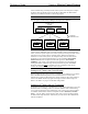
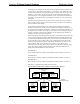
In this example, a system is comprised of three classrooms and a control room.
Each classroom has:
• A PRO2 control system with a C2ENET-1 Ethernet card
• A TPS-5000 with a TPS-VID-1 video card.
• A CPC-CAMI pan/tilt camera head with Pan/Tilt/Focus/Zoom control and
Presets
• A distribution amplifier for sending video signals from the camera to the
TPS-5000 and the control room.
The control room has:
• A PRO2 control system with a C2ENET-1 Ethernet card
• A TPS-5000 with a TPS-VID-1 video card and a TPS-ENET Ethernet card.
• A C2N-MMS Professional Multimedia Switch for switching between the
video signals for each classroom.
Each classroom controls a local camera from the TPS-5000 panel. The TPS-5000
receives video from the camera through the distribution amplifier.
The control room touchpanel communicates via Ethernet to the PRO2 control
systems in each classroom. It can control any of the cameras in those rooms by
communicating directly with the control system in the room. The control room
switches the video feed from the room to itself by using the PRO2 and C2N-MMS
located in the control room.
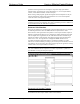
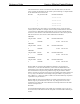
The IP addresses for the Ethernet devices used in the network are:
Network IP Addresses
DEVICE IP ADDRESS
PRO2 in classroom 1 192.168.1.10
PRO2 in classroom 2 192.168.1.11
PRO2 in classroom 3 192.168.1.12
TPS-5000 in control room 192.168.1.14
PRO2 in control room 192.168.1.15
Without JNR