Crestron QM-FTSC FlipTop Storage Center Operations & Installation Guide
This document was prepared and written by the Technical Documentation department at: Crestron Electronics, Inc. 15 Volvo Drive Rockleigh, NJ 07647 1-888-CRESTRON All brand names, product names and trademarks are the property of their respective owners. ©2004 Crestron Electronics, Inc.
Crestron QM-FTSC FlipTop Storage Center Contents FlipTop Storage Center: QM-FTSC 1 Introduction ..........................................................................................................1 Features and Functions...........................................................................1 The QuickMedia Transport System .......................................................2 Specifications .........................................................................................
Crestron QM-FTSC FlipTop Storage Center FlipTop Storage Center: QM-FTSC Introduction Features and Functions The QM-FTSC-B and the QM-FTSC-BALUM are part of the Crestron MediaManager™ line of network devices, room control systems and signal routing solutions. The suffix ‘-B’, and ‘-BALUM’, respectively denotes color, e.g., QM-FTSC-B is a black unit, and QM-FTSC-BALUM has a brushed aluminum finish.
FlipTop Storage Center Crestron QM-FTSC NOTE: The QM-FTSC is compatible with 2-Series control systems only.
Crestron QM-FTSC FlipTop Storage Center The Crescat-QM cable contains one CAT5E cable and one Cresnet® cable in a siamese jacket. If you choose to use Belden MediaTwist or other CAT5E for the AV signals, then you need to install a separate Cresnet cable for control and power. QuickMedia Cable – CRESCAT-QM The pin assignment is based on the EIA/TIA 568B RJ-45 Jack standard.
FlipTop Storage Center Crestron QM-FTSC Specifications Specifications for the QM-FTSC are given in the following table. QM-FTSC Specifications SPECIFICATION DETAILS Power Requirements 8 Watts (0.33 Amp @ 24 VDC) Default Network IDs 04 (QM-WMC/QM-WMIC) 73 (C2N-DB6) Video Formats Composite, S-video, RGBHV Video Detection Within 2 seconds Firmware QM-WMC.V.2.24.upg or later PK_C2NDB6.V1.00a.csf or later 2-Series Control System Update Files1,2 Version 3.093.
Crestron QM-FTSC FlipTop Storage Center QM-FTSC Specifications (continued) SPECIFICATION DETAILS Audio Analog-Digital Conversion 24 bit / 48 kHz Maximum line-level input 2 Vrms/ 6 dBVrms (Video) 1 Vrms/ 0 dBVrms (PC) Input Impedance 10k ohms Bandwidth 20 Hz to 20 kHz Operating Temperature and Humidity 41º to 104º F (5º to 40º C) 10 to 90% relative humidity (non-condensing) Dimensions and Weight Width: 8.26 in (20.98 cm) Height: 6.08 in (15.44 cm) Depth: 6.23 in (15.82 cm) Weight: 8.8 lbs (3.
FlipTop Storage Center Crestron QM-FTSC Physical Dimensions - Top View Bottom View 8.26 in (20.98 cm) 6.23 in (15.82 cm) Back View Right Side View 7.76 in (19.71 cm) 6.08 in (15.44 cm) 5.12 in (13.00 cm) 5.19 in (13.19 cm) 6 • FlipTop Storage Center: QM-FTSC Operations & Installation Guide - DOC.
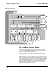
Crestron QM-FTSC FlipTop Storage Center Controls and Ports (Top) Buttons 2 4 6 1 3 5 The QM-FTSC has six buttons. All buttons are functionally identical and have light emitting diodes (LEDs) that serve as user feedback indicators. The illumination of each LED (on/off) is independently addressable, and programmable using SIMPL Windows. In the program, the intensity level for all button LEDs can be set from 0 to 100%. NOTE: Numbers are for programming purposes only.
FlipTop Storage Center Crestron QM-FTSC COMPUTER This female connector is used for connecting a computer’s RGB video output to the presentation system. A corresponding 3.5mm mini-jack is provided for the computer sound card output. This port can automatically detect the presence of an H-sync video signal on pin 15. An LED near the RGB connector indicates the presence of an H-sync signal. Refer to the following table for pinassignments.
Crestron QM-FTSC FlipTop Storage Center NET (x2) NET 24 Y Z G NET 24 Y Z G These two 4-pin terminal block connectors, located on the right side of the QMFTSC, are for connection to the Cresnet network. One connector is used to connect to the Cresnet network while the second connector can be used to connect another Cresnet device. Cresnet power to the QM-FTSC is supplied through either of these connectors. For more information, refer to “Network Wiring” on page 11.
FlipTop Storage Center Crestron QM-FTSC Indicators PWR (Power) This LED illuminates when 24 volts DC is supplied to the QM-FTSC from Cresnet. NET This LED illuminates when communication between the control system and the QM-FTSC is established (the unit is polled on the network). Illumination indicates that the SIMPL Windows program currently loaded has a network device defined at the same Net ID as the QM-FTSC. The LED flashes when communication with the processor occurs.
Crestron QM-FTSC FlipTop Storage Center Setup Network Wiring CAUTION: Provide sufficient power to the system. Insufficient power can lead to unpredictable results or damage to the equipment. Please use the Crestron Power Calculator to help calculate how much power is needed for the system. CAUTION: Use only Crestron power supplies for Crestron equipment. Failure to do so could cause equipment damage or void the Crestron warranty.
FlipTop Storage Center Crestron QM-FTSC becomes brittle. Insert the tinned connection into the Cresnet connector and tighten the retaining screw. Repeat the procedure for the other three conductors. NOTE: For additional information on video connections over CAT5, refer to the latest version of the Crestron CAT5 Wiring Reference Guide (Doc. 6137) which is available from the Downloads | Product Manuals section of the Crestron website (www.crerstron.com). NOTE: For larger networks (i.e.
Crestron QM-FTSC FlipTop Storage Center 3. From the Viewport menu, select Functions | Set Network ID. The software checks the baud rate and then opens the "Set Network ID" window. 4. In the "Set Network ID" window, select the device requiring a Net ID change from the Current Network Devices text window. 5. Select the new Net ID for the device from the Choose the new network ID for the selected device (Hex): text box. 6. Click Set ID to initiate the change.
FlipTop Storage Center Crestron QM-FTSC “Set Net ID by TSID” Window 5. Enter either the serial number or TSID number of the device that requires a change. The list scrolls to and highlights the device listing. The listing should show the device’s default Cresnet ID (a.k.a. Net ID). 6. Enter the Cresnet ID that the device should be set to and click OK. The number you enter should appear on the list. CAUTION: This function does not prevent you from setting duplicate IDs.
Crestron QM-FTSC FlipTop Storage Center 3. Enter the serial number or TSID number as instructed; press the appropriate button to obtain the corresponding number. NOTE: Enter serial numbers, including spaces, exactly as they appear on the unit label. Alpha characters in serial numbers or TSID numbers may be entered in upper or lower case. Installation Supplied Parts Part Quantity Small Cable Bushing, 5/16 inch ID, 0.5 inch OD 8 Large cable Bushing, 0.55 inch ID, 0.
FlipTop Storage Center Crestron QM-FTSC Cable Plate Installation Cable Support Plate Bushing (4) #4 x 3/16 LG Black Screws Cable Tie Wrap Location Connected Cable End Bar Tie Wrap Cable Passed Through Cable Support Plate Excess Cable Loop 16 • FlipTop Storage Center: QM-FTSC Operations & Installation Guide - DOC.
Crestron QM-FTSC FlipTop Storage Center Mounting to Surface The QM-FTSC is designed to mount in a horizontal surface, such as a desk top, lectern, or podium. The following diagram illustrates the required opening size to accommodate the QM-FTSC. Mounting Hole Dimensions 7.88 in (20.00 cm) 5.88 in (14.92 cm) Radius 0.125 in (0.318 cm) NOTE: Before inserting the QM-FTSC in the mounting hole, ensure that all required cables have been installed. 1.
FlipTop Storage Center Crestron QM-FTSC 3. Install the four #10 screws in the mounting brackets (two screws per bracket). Refer to the following diagram. 4. Slide the mounting brackets over the #6-32 screws and tighten the #632 screws. 5. Turn the four #10 screws equally until they contact the underside of the mounting surface. NOTE: Do not over-tighten the #10 screws as this may damage the surface and/or the unit.
Crestron QM-FTSC FlipTop Storage Center NOTE: The maximum continuous current from equipment under any external load conditions shall not exceed a current limit that is suitable for the minimum wire gauge used in interconnecting cables. The ratings on the connecting unit's supply input should be considered to prevent overloading the wiring.
FlipTop Storage Center Crestron QM-FTSC Ground Wire Connections Proper grounding is required. Connect the ground from the QM transmitter (QM-FTSC) to earth ground. Connect the Cresnet shield at the QM-RMCRX to the chassis ground provided on the QM-RMCRX. The QM-RMCRX chassis must also be connected to an earth ground (building steel). Refer to the following grounding diagram.
Crestron QM-FTSC FlipTop Storage Center Earliest Version Software Requirements for the PC NOTE: Crestron recommends the use of SystemBuilder and Digital Media Tools software for creating and fine-tuning a QuickMedia system. NOTE: Crestron recommends that you use the latest software to take advantage of the most recently released features. The latest software is available from the Downloads | Software Updates section of the Crestron website (www.crestron.com).
FlipTop Storage Center Crestron QM-FTSC SystemBuilder When you click New, you can choose the QuickMedia Solutions tab. This tab offers a choice of wizard solutions. The Single Origination Point Wizard was designed to rapidly and simply create a system configuration that has a single QuickMedia origination point (QMFTSC) connected to a single QuickMedia destination (QM-RMCRX in this example). Configuration includes display control programming, audio and video routing, keypad controls, and room management.
Crestron QM-FTSC FlipTop Storage Center • Room Options – Permits the use of RoomView management software, and sets the administrator and user passwords. • Audio Options – Type of audio, program source or program and speech source. • User Interfaces – Button layout and designations (six button equal to the top portion of the QM-FTSC). • Controlled Sources –Select source devices from the extensive database and assign control parameters.
FlipTop Storage Center Crestron QM-FTSC Configuring with SIMPL Windows NOTE: While SIMPL Windows can be used to configure the QM-FTSC, Crestron recommends SystemBuilder and Digital Media Tools software for configuring and tuning a QuickMedia system. NOTE: The following are acceptable file extensions for programs that include a QM-RMCRX and QM-FTSC, developed for specific control system types: .smw projectname.smw (source file) .spz projectname.spz (compiled file for 2-Series) .usp projectname.
Crestron QM-FTSC FlipTop Storage Center System View of QM-RMCRX C2Net-Device Slot in Configuration Manager The C2Net-Device slot (05) enables the QM-RMCRX to control up to 252 Cresnet devices. Each Cresnet device is assigned a unique identifier called a Net ID, which is a hexadecimal value ranging from 03 to FE.
FlipTop Storage Center Crestron QM-FTSC C2Net-Device, Slot 5 Setting the Net ID in Device Settings Double-click the QM-FTSC icon in the upper pane to open the “Device Settings” window. This window displays QM-FTSC device information. The Net ID can be changed in this window using the Net ID tab, as shown in the following figure. “Device Settings” Window NOTE: This procedure sets the Net ID for the QM-FTSC in the program only. It does not automatically set the Net ID for the QM-FTSC itself.
Crestron QM-FTSC FlipTop Storage Center Basic Controls QM-WMC Symbol – Detail View of Basic Controls The following tables list the symbol’s input and output signals, respectively, and their functional descriptions. QM-WMC Analog Input Signal Descriptions INPUT DESCRIPTION VidInput Select Selects the video source to be used. AudInput Select Selects the audio source to be used. Signal Values for “VidInput Select” SIGNAL VALUE SOURCE 1 Selects RGB input. 2 Selects composite video input.
FlipTop Storage Center Crestron QM-FTSC QM-WMC Digital Output Signal Descriptions OUTPUT DESCRIPTION RGB Detect Goes high when RGB signal is detected. Composite Detect Goes high when video signal is detected. Svideo Detect Goes high when luminance signal is detected. QM-WMC Analog Output Signal Descriptions OUTPUT DESCRIPTION VidInput Select-F Indicates the video source that is selected. AudInput Select-F Indicates the audio source that is selected.
Crestron QM-FTSC FlipTop Storage Center QM-WMIC Digital Input Signal Descriptions INPUT DESCRIPTION Mic1Mute Mutes the input signal from Mic 1 when high. Mic2Mute Mutes the input signal from Mic 2 when high. Mic1GatingEnable Enables automatic gating on Mic 1 when high. Mic2GatingEnable Enables automatic gating on Mic 2 when high. PhantomEnable Enables phantom power for both microphone inputs when high. NOTE: Phantom power is applied to the XLR connectors of both microphone inputs.
FlipTop Storage Center Crestron QM-FTSC NOTE: Nominal indication is reported at 20 dB below input clip level. Clip indication is reported at 6 dB below input clip level. QM-WMIC Analog Output Signal Descriptions OUTPUT DESCRIPTION Mic1GatingLevel-F Gating level feedback for Mic 1. Mic2GatingLevel-F Gating level feedback for Mic 2. Mic1Gain-F Gain level feedback for Mic 1. Mic2Gain-F Gain level feedback for Mic 2. AttackTime-F Attack time setting feedback.
Crestron QM-FTSC FlipTop Storage Center Programming with VisionTools Pro-e Touchpanel screens can be created in VT Pro-e to allow configuration of phantom power, gain levels, gating levels, attack times, and decay times. Digital Media Tools software already has these controls built in. Refer to the following section “Adjusting the QM-FTSC Microphone Inputs” for additional information. Example Program An example program for the QM-FTSC is available from the Crestron FTP site (ftp://ftp.crestron.
FlipTop Storage Center Crestron QM-FTSC Visual Representation of Gating Level, Clipping Level, Attack Time, and Decay Time SIGNAL LEVEL MICROPHONE INPUT SIGNAL Clipping Level Mic On Gating Level Mic Off TIME Attack Time Decay Time SIGNAL LEVEL QM OUTPUT SIGNAL Gating Level Reached Gating Level Reached Mic On Mic Off TIME Attack Time Decay Time Setting Microphone Gain The QM-FTSC provides variable gain on the XLR and ¼” microphone inputs.
Crestron QM-FTSC FlipTop Storage Center NOTE: The input gain is independent of the system’s output volume level. 1. To adjust the input gain, set the gain and noise gate to their lowest settings. Disable the “Mute” function by removing the check from the Mute checkbox. 2. Connect a microphone and enable phantom power if required. 3. Increase the gain while providing a “normal” sound level input to the microphone.
FlipTop Storage Center Crestron QM-FTSC Uploading and Upgrading Assuming a PC is properly connected to the entire system, Crestron programming software allows the programmer to upload programs and projects to the system and touchpanel and firmware to the wall plates after their development. However, there are times when the files for the program and projects are compiled and not uploaded. Instead, compiled files may be distributed from programmers to installers, from Crestron to dealers, etc.
Crestron QM-FTSC FlipTop Storage Center Typical Connection Diagram when Uploading QM-FTSC Cresnet Cable QuickMedia Cable QM-RMCRX (Front) QM-RMCRX (Rear) Computer Null-modem RS-232 cable with DB9 female connectors on both ends NOTE: Use a standard DB9 “Null-Modem” cable. NOTE: QuickMedia cable is CAT5E type. The total accumulated skew from QM transmitter to QM receiver must not exceed 15 ns (nanoseconds).
FlipTop Storage Center Crestron QM-FTSC Setup | Communications Settings Command 3. Select RS-232 as the connection type. Verify that an available COM port (COM 1 is shown after this step) is selected, and that all communication parameters and necessary options from the “Port Settings” window are selected as shown after this step. Click the OK button to save the settings and close the window.
Crestron QM-FTSC FlipTop Storage Center Uploading a SIMPL Windows Program A control system source file has the extension .smw. A compiled SIMPL Windows file has the extension .spz for a 2-Series control system. The SIMPL Windows file can be uploaded to the control system using SIMPL Windows or via the Crestron Viewport. Upload via SIMPL Windows 1. Start SIMPL Windows. 2. Select File | Open to view the “Open” window, navigate to the SIMPL Window file (.smw), and click Open. 3.
FlipTop Storage Center Crestron QM-FTSC “Send Program” Window 4. To verify that the program has been transferred successfully, select Diagnostics | Report Program Information. This should display a window that provides details about the current program loaded into the control system. Firmware Upgrade A firmware upgrade file has the extension .csf. To take advantage of all the QM-FTSC features, it is important that the unit contains the latest firmware available.
Crestron QM-FTSC FlipTop Storage Center File Transfer | Load Network Device… Command 3. As shown in the “Select Network ID” window, select the Net ID of the QM-WMC portion of the QM-FTSC, and then click OK. The “Open” window appears (refer to the following graphics). “Select Network ID” Window NOTE: If problems arise when transferring any Cresnet file (touchpanel project/firmware), lower the port speed baud rate to 38400 to match the Cresnet bus speed. Operations & Installation Guide – DOC.
FlipTop Storage Center Crestron QM-FTSC “Open” Window 4. Browse to the desired [filename].upg file and click Open to begin the transfer. Button Panel Firmware To upgrade the Button Panel firmware, complete the following steps. 1. Make sure that “Communication Settings,” which begins on page 20, has been performed. 2. As shown after this step, select File Transfer | Update Touchpanel/Keypad Firmware from the Viewport menu bar. File Transfer | Update Touchpanel/Keypad Firmware Command 3.
Crestron QM-FTSC FlipTop Storage Center “Select Network ID” Window NOTE: When transferring a Cresnet file (touchpanel project/ firmware), lower the port speed baud rate to 38400 to match the Cresnet bus speed. “Open” Window NOTE: Firmware upgrades to the button panel include two files, [filename]a.csf and [filename]b.csf. Select the ‘a’ file to begin the upload; the ‘b’ file is loaded automatically. 4. Browse to the desired [filename]a.csf file and click Open to begin the transfer.
FlipTop Storage Center Crestron QM-FTSC QM-FTSC Troubleshooting TROUBLE QM-FTSC not functioning. POSSIBLE CAUSE(S) CORRECTIVE ACTION Net ID is not correct. In Viewport, poll the network to verify the Net ID. Net ID is not set to match the Net ID specified in SIMPL Windows. Verify SIMPL Windows program for setting Net ID. Net ID is the same as another device’s Net ID. Assign a different Net ID. PWR LED does not illuminate. Not receiving power. Verify that the plug is properly attached.
Crestron QM-FTSC FlipTop Storage Center Troubleshooting (continued) TROUBLE POSSIBLE CAUSE(S) CORRECTIVE ACTION Microphone produces harsh, distorted sound. Input gain is set too high. Lower microphone input gain. Buttons do not function when pressed. Net ID incorrect or does not match SIMPL Windows program. In Viewport, press F4 to verify Net ID. Verify SIMPL Windows program ID. Button press yields incorrect result. Incorrect programming. Verify SIMPL Windows program.
FlipTop Storage Center Crestron QM-FTSC Return and Warranty Policies Merchandise Returns / Repair Service 1. No merchandise may be returned for credit, exchange, or service without prior authorization from CRESTRON. To obtain warranty service for CRESTRON products, contact the factory and request an RMA (Return Merchandise Authorization) number. Enclose a note specifying the nature of the problem, name and phone number of contact person, RMA number, and return address. 2.
Crestron QM-FTSC FlipTop Storage Center This page intentionally left blank. Operations & Installation Guide – DOC.
FlipTop Storage Center Crestron QM-FTSC This page intentionally left blank. 46 • FlipTop Storage Center: QM-FTSC Operations & Installation Guide - DOC.
Crestron QM-FTSC FlipTop Storage Center This page intentionally left blank. Operations & Installation Guide – DOC.
Crestron Electronics, Inc. 15 Volvo Drive Rockleigh, NJ 07647 Tel: 888.CRESTRON Fax: 201.767.7576 www.crestron.com Operations & Installation Guide – DOC. 6269 05.04 Specifications subject to change without notice.