
Specifications
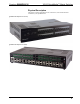


Crestron QM-MD16X16 16X16 QuickMedia™ Matrix Switcher
Hardware Hookup
Connect the Device
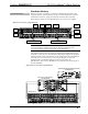
Make the necessary connections as called out in the illustration that follows this
paragraph. Refer to “Network Wiring” on page 12 before attaching the 4-position
terminal block connector. Apply power after all connections have been made.
When making connections to the QM-MD16X16, use Crestron power supplies.
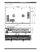
Hardware Connections for the QM-MD16X16
CRESNET:
CONNECT TO
THE CRESNET
CONTROL
NETWORK
POWER:
24 VDC TO
QM INPUTS
1 - 4
POWER:
24 VDC TO
QM INPUTS
5-8
POWER:
24 VDC TO
QM INPUTS
13-16
POWER:
24 VDC TO
QM INPUTS
9-12
QM INPUTS:
QUICKMEDIA PORT CARRIES AUDIO, VIDEO,
RGB, AND MICROPHONE SIGNALS
QM OUTPUTS:
QUICKMEDIA PORT CARRIES AUDIO, VIDEO,
RGB, AND MICROPHONE SIGNALS
POWER:
24 VDC TO
QM OUTPUTS
5-8
POWER:
24 VDC TO
QM OUTPUTS
1-4
POWER:
24 VDC TO
QM OUTPUTS
9-12
POWER:
24 VDC TO
QM OUTPUTS
13-16
NOTE: For optimum performance, Crestron strongly recommends using
CresCAT-QM cable, available from Crestron. Other high-quality/low skew
CAT5e/CAT6 wiring may also be used with varying performance.
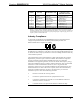
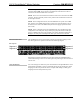
The required 24 VDC power for each group of QM inputs and QM outputs can be
supplied in a variety of ways. The following wiring diagram suggests one method of
applying 24 VDC power to the QM ports. In this configuration, the C2N-SPWS300
can supply up to 75 watts of power to each group of QM ports to ensure that
sufficient power is available for QM devices that are connected to the
QM-MD16X16. Power for the QM-MD16x16 is jumped from the Cresnet input on
the C2N-SPWS300.
Suggested Power Connections for QM-MD16X16
QM-MD16X16
QUICKMEDIA RECEIVER/PROCESSOR
QM-RMCRX-BA
300 WATT POWER SUPPLY
C2N-SPWS300
Operations Guide – DOC. 6538A 16X16 QuickMedia™ Matrix Switcher: QM-MD16X16 • 15