Crestron QM-WMC, QM-WMC-VCC & QM-WCC-2 Wall Plate Media & Computer Centers Operations & Installation Guide
This document was prepared and written by the Technical Documentation department at: Crestron Electronics, Inc. 15 Volvo Drive Rockleigh, NJ 07647 1-888-CRESTRON Regulatory Compliance As of the date of manufacture, the QM-WMC/WMC-VCC/WCC-2 has been tested and found to comply with specifications for CE marking and standards per EMC and Radiocommunications Compliance Labelling. Federal Communications Commission (FCC) Compliance Statement This device complies with part 15 of the FCC Rules.
Crestron QM-WMC/WMC-VCC/WCC-2 Media & Computer Centers Contents Wall Plate Media & Computer Centers: QM-WMC, QM-WMC-VCC & QM-WCC-2 1 Introduction ............................................................................................................................... 1 Features and Functions ................................................................................................ 2 Applications.....................................................................................................
Crestron QM-WMC/WMC-VCC/WCC-2 Media & Computer Centers Wall Plate Media & Computer Centers: QM-WMC, QM-WMC-VCC & QM-WCC-2 Introduction Crestron’s MediaManager is a comprehensive family of affordable products fusing high performance AV signal distribution, device control and facility-wide system management. MediaManager simplifies the art of Pro AV system design and installation with complete hardware, software and low-cost wiring solutions.
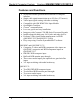
Media & Computer Centers Crestron QM-WMC/WMC-VCC/WCC-2 Features and Functions • Stylish wall mount QuickMedia multimedia or computer interface • Single cable signal transmission up to 450 feet (137 meters) • Video input signal sensing with auto-switching • Compatible with QM-WMIC Mic Input Module • QuickMedia Transport • Cresnet® communications • Low-cost, quick and easy installation • Integrates with Crestron C2N-DB Series Decorator Keypads • Installs alongside third-party LAN jacks and other devices • P
Crestron QM-WMC/WMC-VCC/WCC-2 Media & Computer Centers Wall Mount Multimedia Interface (QM-WMC & QM-WMC-VCC only) The QM-WMC and QM-WMC-VCC install cleanly in a standard twogang electrical box using a decorator style faceplate (not supplied). Individual video inputs are provided for composite, S-video* and RGB/component signals, each with corresponding stereo audio, to accept connections from portable AV devices and computers.
Media & Computer Centers Crestron QM-WMC/WMC-VCC/WCC-2 The built-in 2x1 switcher in the QM-WCC-2 includes audio breakaway to allow two PC audio inputs to be switched independent of their corresponding RGB inputs or linked with them. Built-in video sensing on each RGB input can be utilized to trigger automatic input selection and power control. Gated Mic Preamp (Optional) Two gated microphone inputs may be added using the QM-WMIC Microphone Input Module (sold separately).
Crestron QM-WMC/WMC-VCC/WCC-2 Media & Computer Centers easy to design, program and adjust from start to finish using Crestron SystemBuilder software. EDID Format Management (QM-WMC-VCC and QM-WCC-2 only) The QM-WMC-VCC and the QM-WCC-2 allow for management of the EDID (Extended Display Identification Data) information sent to the connected source.
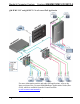
Media & Computer Centers Crestron QM-WMC/WMC-VCC/WCC-2 QM-WMC-VCC and QM-WCC-2 in a Lecture Hall Application For more information on this and other QM applications, refer to the latest revision of the Crestron MediaManager Applications Guide (Doc. 6244), which is available from the Crestron website (www.crestron.com/manuals). 6 • Wall Plate Media & Computer Centers Operations & Installation Guide – DOC.
Crestron QM-WMC/WMC-VCC/WCC-2 Media & Computer Centers Internal Block Diagram The following diagrams represent the operational abilities of the QM-WMC, QM-WMC-VCC and QM-WCC-2 with the optional QM-WMIC. Internal Block Diagram of the QM-WMC (with QM-WMIC) QM-WMC Monitor Buffer Computer 3x1 Video Switch S-video QM Combiner QM Out RJ-45 Video 3x1 Audio Switch A/D Audio Encoder Phantom Mic 1 Gain A/D Gate Mic 2 Gain A/D Gate Operations & Installation Guide – DOC.
Media & Computer Centers Crestron QM-WMC/WMC-VCC/WCC-2 Internal Block Diagram of the QM-WMC-VCC (with QM-WMIC) QM-WMC-VCC Monitor Buffer Computer 3x1 Video Switch Componet YPbBr QM Combiner QM Out RJ-45 Composite 3x1 Audio Switch Audio Encoder A/D Phantom Mic 1 Gain A/D Gate Mic 2 Gain A/D Gate Internal Block Diagram of the QM-WCC-2 (with QM-WMIC) QM-WCC-2 Monitor Buffer PC 1 RGBHV w/Audio Buffer 2x1 Video Switch PC 2 RGBHV w/Audio 2x1 Audio Switch A/D Monitor QM Combiner QM Out RJ
Crestron QM-WMC/WMC-VCC/WCC-2 Media & Computer Centers Specifications Specifications for the QM-WMC/WMC-VCC/WCC-2 are listed in the following table.
Media & Computer Centers Crestron QM-WMC/WMC-VCC/WCC-2 QM-WMC/WMC-VCC/WCC-2 Specifications (Continued) SPECIFICATION Environmental Temperature Humidity Heat Dissipation QM-WMC QM-WMC-VCC & QM-WCC-2 Enclosure Dimensions Height Width Depth QM-WMC QM-WMC-VCC QM-WCC-2 Weight QM-WMC & QM-WMC-VCC QM-WCC-2 Available Accessories QM-WMIC DETAILS 41º to 104º F (5º to 40º C) 10% to 90% RH (non-condensing) 17 BTU/Hr 21 BTU/Hr Two-gang mountable in a 2.5 in (6.
Crestron QM-WMC/WMC-VCC/WCC-2 Media & Computer Centers NOTE: Crestron software and any files on the website are for authorized Crestron dealers and Crestron Authorized Independent Programmers (CAIP) only. New users may be required to register to obtain access to certain areas of the site (including the FTP site). Physical Description This section provides information on the connections, controls and indicators available on your QM-WMC/WMC-VCC/WCC-2.
Media & Computer Centers Crestron QM-WMC/WMC-VCC/WCC-2 QM-WMC-VCC Physical View 12 • Wall Plate Media & Computer Centers Operations & Installation Guide – DOC.
Crestron QM-WMC/WMC-VCC/WCC-2 Media & Computer Centers QM-WCC-2 Physical View Operations & Installation Guide – DOC.
Media & Computer Centers Crestron QM-WMC/WMC-VCC/WCC-2 QM-WMC Overall Dimensions (Front and Side Views) QM-WMC-VCC Overall Dimensions (Front and Side Views) 14 • Wall Plate Media & Computer Centers Operations & Installation Guide – DOC.
Crestron QM-WMC/WMC-VCC/WCC-2 Media & Computer Centers QM-WCC-2 Overall Dimensions (Front and Side Views) QM-WMC/WMC-VCC/WCC-2 Overall Dimensions (Rear View) Operations & Installation Guide – DOC.
Media & Computer Centers Crestron QM-WMC/WMC-VCC/WCC-2 Connectors, Controls & Indicators # CONNECTORS1, CONTROLS & INDICATORS 1 S-VIDEO2 DESCRIPTION (1) 4-pin mini DIN female, S-video (Y/C) input Input impedance: 75 Ω Maximum input: level: 1 Vp-p Signal sensing on Y 2 4 1 3 S-video DIN Connector Pin Assignments 2 AUDIO (S-video)2 3 AUDIO (video)2 AUDIO (composite)3 4 VIDEO2 VID (COMPOSITE)3 PIN DESCRIPTION 1 Luminance Ground 2 Chrominance Ground 3 Luminance 4 Chrominance (2) RCA
Crestron QM-WMC/WMC-VCC/WCC-2 Media & Computer Centers Connectors, Controls & Indicators (Continued) # CONNECTORS1, CONTROLS & INDICATORS 5 AUDIO 6 MONITOR4 7 PWR LED 8 NET LED 9 COMPUTER2 10 SETUP (Button and LED) DESCRIPTION (1) 3.
Media & Computer Centers Crestron QM-WMC/WMC-VCC/WCC-2 Connectors, Controls & Indicators (Continued) # CONNECTORS1, CONTROLS & INDICATORS DESCRIPTION 11 COMP2 / PC3 / PC (1–2)6 LED 12 VIDEO2 / VID3 LED 13 S-VID2 LED 14 COMPONENT3 (1) Red LED, indicates a signal at the COMPUTER, PC or PC (1-2) input (1) Red LED, indicates a signal at the VIDEO or COMPOSITE input (1) Red LED, indicates a signal at the S-VIDEO input (3) RCA female, component video input; Formats: YPbPr, Y/C7; Input impedance: 75
Crestron QM-WMC/WMC-VCC/WCC-2 Media & Computer Centers Connectors, Controls & Indicators (Continued) # CONNECTORS1, CONTROLS & INDICATORS DESCRIPTION 18 NET 19 TO MIC (2) Four-position terminal block connectors for data and power.
Media & Computer Centers Crestron QM-WMC/WMC-VCC/WCC-2 aggregate cable length and delay skew between any QM transmitter (origination point) and QM receiver (endpoint) is 450 feet (137 meters) and 22 ns; a maximum of two QM midpoint devices may be inserted in a given QM signal path; exceptions apply, refer to each respective product manual for details. 10. The eight-pin RJ-45 QuickMedia transport port accepts CAT5E/CAT6 carrying audio, video and microphone signals.
Crestron QM-WMC/WMC-VCC/WCC-2 Media & Computer Centers Setup Network Wiring When wiring the Cresnet® network, consider the following: • Use Crestron Certified Wire. • Use Crestron power supplies for Crestron equipment. • Provide sufficient power to the system. CAUTION: Insufficient power can lead to unpredictable results or damage to the equipment. Please use the Crestron Power Calculator to help calculate how much power is needed for the system (www.crestron.com/calculators).
Media & Computer Centers Crestron QM-WMC/WMC-VCC/WCC-2 CresCAT-QM Cable CresCAT-QM Cable NOTE: Do not untwist the two wires in a single pair for more than 1/31/2” (8 - 13 mm) when making a connection. The twists are critical to canceling out interference between the wires. The aggregate cable length of a signal path originating at a QM-WMC/WMC-VCC/WCC-2 and terminating at a QM receiver must not exceed 450 feet (137 meters). Video signals may experience a loss of quality over very long lengths of cable.
Crestron QM-WMC/WMC-VCC/WCC-2 Media & Computer Centers When connecting multiple QM devices, the route between a QM origination point (transmitter) and a QM endpoint (receiver) cannot have more than two midpoints (e.g. QM-MD7x2 or other QM switchers). Refer to the following diagram when configuring a QM network. NOTE: The aggregate length from transmitter to receiver cannot have a delay skew of more than 22 ns per 100 meters.
Media & Computer Centers Crestron QM-WMC/WMC-VCC/WCC-2 Installation NOTE: If the QM-WMIC is to be used, refer to the installation instructions in the latest revision of the QM-WMIC Operations and Installation Guide (Doc. 6245) which is available from the Crestron website. The QM-WMC/WMC-VCC/WCC-2 should be used in a well-ventilated area. The venting holes should not be obstructed under any circumstances.
Crestron QM-WMC/WMC-VCC/WCC-2 Media & Computer Centers 4. Remove the pre-cut insulation from the QM-WMC/WMC-VCC/WCC-2’s grounding wire on the back of the device and connect the grounding wire to an appropriate ground. (Refer to illustration on page 27 for location of the grounding wire.) Suitable grounding methods are: • Connect the grounding wire to the electrical box or a ground wire in the electrical box, as shown in the following illustration. (The electrical box must be earth grounded.
Media & Computer Centers Crestron QM-WMC/WMC-VCC/WCC-2 Grounding the QM-WMC/WMC-VCC/WCC-2 Using Cresnet Shield to Grounded Chassis (QM-WMC Shown) Electrical Box Isolated from Ground QM-RMCRX-BA or CP2, CP2E, MC2E, MC2W, MP2, MP2E 24 Y QM-WMC Z G Shield 24 VDC Chassis To Earth Ground Grounding Wire Line Voltage NOTE: When the Cresnet shield is used to connect the QM-WMC/WMC-VCC/WCC-2 to the ground terminal of a PRO2, PAC2, AV2 or any other 2-Series control system where the chassis is already earth
Crestron QM-WMC/WMC-VCC/WCC-2 Media & Computer Centers Cresnet Ports, QuickMedia Port and Grounding Lead Locations Remove pre-cut insulation and connect this grounding wire to ground. QuickMedia Port Cresnet Port 5. Make sure the QM-WMC/WMC-VCC/WCC-2 is properly oriented (labels are upright) and place it in the electrical box. CAUTION: Excess wire that is pinched between the QM-WMC/WMC-VCC/WCC-2 and the electrical box could short out.
Media & Computer Centers Crestron QM-WMC/WMC-VCC/WCC-2 Install QM-WMC/WMC-VCC/WCC-2 into Two-Gang Electrical Box (QM-WMC Shown) Electrical Box (Not Supplied) Minimum Depth 2.5 In (64 mm) Screws (4) #06-32 X 3/4" (Supplied) 7. Attach an appropriate decorator style or equivalent faceplate (not supplied). 8. Turn Cresnet system power ON. Hardware Hookup Make the necessary connections as called out in the illustrations that follow this paragraph.
Crestron QM-WMC/WMC-VCC/WCC-2 Media & Computer Centers Hardware Connections for the QM-WMC AUDIO (computer): Stereo Line Level Audio From PC S-VIDEO: From S-video Source MONITOR: Buffered RGBHV Pass-Through to PC AUDIO (S-video): Stereo Audio From S-video Source VIDEO: From Composite Video Source COMPUTER: RGB (VGA)/Component Video From PC AUDIO (video): Stereo Audio From Composite Source Hardware Connections for the QM-WMC-VCC AUDIO (component): Stereo Audio From Component Source COMPONENT: From Comp
Media & Computer Centers Crestron QM-WMC/WMC-VCC/WCC-2 Hardware Connections for the QM-WCC-2 AUDIO (computer): Stereo Line Level Audio From PC AUDIO (computer): Stereo Line Level Audio From PC MONITER: Buffered RGBHV Pass-Through to PC MONITOR: Buffered RGBHV Pass-Through to PC PC: RGB (VGA) Video From PC PC: RGB (VGA) Video From PC Hardware Connections for the QM-WMC/WMC-VCC2/WCC-2 (Rear View) CRESNET: To Control System and Other Cresnet Devices TO MIC: From QM-WMIC Microphone Input Module QM: Qu
Crestron QM-WMC/WMC-VCC/WCC-2 Media & Computer Centers Programming Software Have a question or comment about Crestron software? Answers to frequently asked questions (FAQs) can be viewed in the Online Help section of the Crestron website. To post a question or view questions you have submitted to Crestron’s True Blue Support, log in at http://support.crestron.com. First-time users will need to establish a user account.
Media & Computer Centers Crestron QM-WMC/WMC-VCC/WCC-2 Configuration Configuration Manager is the view where programmers “build” a Crestron control system by selecting hardware from the Device Library. Manager • To incorporate the QM-WMC/WMC-VCC/WCC-2 into the system, drag the QM-WMC/WMC-VCC/WCC-2 from the Cresnet Control Modules | QM Series folder of the Device Library and drop it in the System Views.
Crestron QM-WMC/WMC-VCC/WCC-2 Media & Computer Centers • Additional QM-WMC/WMC-VCC/WCC-2 devices are assigned different Net ID numbers as they are added. • If necessary, double click a device to open the “Device Settings” window and change the Net ID, as shown in the following figure. “QM-WMC/WMC-VCC/WCC-2 Device Settings” Window (QM-WMC Shown) • The ID code specified in the SIMPL Windows program must match the Net ID of each unit. Refer to “Identity Code” on page 23.
Media & Computer Centers Crestron QM-WMC/WMC-VCC/WCC-2 Uploading and Upgrading Crestron recommends using the latest programming software and that each device contains the latest firmware to take advantage of the most recently released features. However, before attempting to upload or upgrade it is necessary to establish communication. Once communication has been established, files (for example, programs or firmware) can be transferred to the control system (and/or device).
Crestron QM-WMC/WMC-VCC/WCC-2 Media & Computer Centers • Display the QM-WMC/WMC-VCC/WCC-2’s “System Info” icon); communications are confirmed when window (click the the device information is displayed. Programs and Firmware Program or firmware files may be distributed from programmers to installers or from Crestron to dealers. Firmware upgrades are available from the Crestron website as new features are developed after product releases.
Media & Computer Centers Crestron QM-WMC/WMC-VCC/WCC-2 Problem Solving Troubleshooting The following table provides corrective action for possible trouble situations. If further assistance is required, please contact a Crestron customer service representative. QM-WMC/WMC-VCC/WCC-2 Troubleshooting TROUBLE POSSIBLE CAUSE(S) CORRECTIVE ACTION Device does not function. Device is not communicating with the network. Use Crestron Toolbox to poll the network. Verify network connection to the device.
Crestron QM-WMC/WMC-VCC/WCC-2 Media & Computer Centers QM-WMC/WMC-VCC/WCC-2 Troubleshooting (Continued) TROUBLE POSSIBLE CAUSE(S) PWR LED does not illuminate. Source LEDs do not illuminate. Device is not receiving power. Sources are not transmitting signals. Poor input connections, QM connections or not programmed in system. Device is powered up and reporting to Cresnet but not switching signals. Intermittent or no Incorrect peak audio output. setting. Poor RGB or video image quality.
Media & Computer Centers Crestron QM-WMC/WMC-VCC/WCC-2 Check Network Wiring Use the Right Wire In order to ensure optimum performance over the full range of your installati topology, Crestron Certified Wire and only Crestron Certified Wire may be used. Failure to do so may incur additional charges if support is required to identify performance deficiencies because of using improper wire. Calculate Power CAUTION: Use only Crestron power supplies for Crestron equipment.
Crestron QM-WMC/WMC-VCC/WCC-2 Media & Computer Centers NOTE: All Crestron certified Cresnet wiring must consist of two twisted pairs. One twisted pair is the +24V conductor and the GND conductor and the other twisted pair is the Y conductor and the Z conductor. Strip and Tin When daisy-chaining Cresnet units, strip the ends of the wires carefully to avoid nicking the conductors. Twist together the ends of the wires that share Wire a pin on the network connector and tin the twisted connection.
Media & Computer Centers Crestron QM-WMC/WMC-VCC/WCC-2 You can also log onto the online help section of the Crestron website (www.crestron.com/onlinehelp) to ask questions about Crestron products. First-time users will need to establish a user account to fully benefit from all available features. Future Updates As Crestron improves functions, adds new features and extends the capabilities of the QM-WMC/WMC-VCC/WCC-2, additional information may be made available as manual updates.
Crestron QM-WMC/WMC-VCC/WCC-2 Media & Computer Centers Return and Warranty Policies Merchandise Returns / Repair Service 1. No merchandise may be returned for credit, exchange or service without prior authorization from CRESTRON. To obtain warranty service for CRESTRON products, contact an authorized CRESTRON dealer. Only authorized CRESTRON dealers may contact the factory and request an RMA (Return Merchandise Authorization) number.
Media & Computer Centers Crestron QM-WMC/WMC-VCC/WCC-2 This page is intentionally left blank. 42 • Wall Plate Media & Computer Centers Operations & Installation Guide – DOC.
Crestron QM-WMC/WMC-VCC/WCC-2 Media & Computer Centers This page is intentionally left blank. Operations & Installation Guide – DOC.
Crestron Electronics, Inc. 15 Volvo Drive Rockleigh, NJ 07647 Tel: 888.CRESTRON Fax: 201.767.7576 www.crestron.com Operations & Installation Guide – DOC. 6237C (2009576) 07.10 Specifications subject to change without notice.