
Installation guide


Crestron QM-WMC/WMC-VCC/WCC-2 Media & Computer Centers
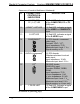
Connectors, Controls & Indicators (Continued)
# CONNECTORS
1
,
CONTROLS &
INDICATORS
DESCRIPTION
5 AUDIO
(1) 3.5 mm TRS mini phone
jack;
Unbalanced stereo line level
audio input;
Input impedance: 10 kΩ;
Maximum input level: 1 V
rms
6 MONITOR
4
DB15HD female, buffered
RGBHV pass-through
7 PWR LED (1) Green LED, indicates 24
Volts DC power supplied from
Cresnet network
8 NET LED (1) Yellow LED, indicates
communication with Cresnet
system
9 COMPUTER
2
(1) DB15HD female;
RGB(VGA)/component video
5
input;
Formats: RGBHV, RGBS,
RGsB, YP
b
P
r
;
Input impedance: 75 Ω
H sync impedance: 1 kΩ
V sync impedance: 2.2 kΩ
Maximum input: level: 1 V
p-p
Maximum sync level: 5 V
p-p
Signal sensing on H sync only
10 SETUP
(Button and LED)
(1) Miniature pushbutton and
red LED, used for
touch-settable ID (TSID)
(Continued on following page)
Operations & Installation Guide – DOC. 6237C Wall Plate Media & Computer Centers • 17