
Installation guide


Media & Computer Centers Crestron QM-WMC/WMC-VCC/WCC-2
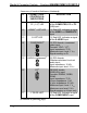
Connectors, Controls & Indicators (Continued)
# CONNECTORS
1
,
CONTROLS &
INDICATORS
DESCRIPTION
11 COMP
2
/ PC
3
/
PC (1–2)
6
LED
(1) Red LED, indicates a signal
at the COMPUTER, PC or PC
(1-2) input
12 VIDEO
2
/ VID
3
LED (1) Red LED, indicates a signal
at the VIDEO or COMPOSITE
input
13 S-VID
2
LED (1) Red LED, indicates a signal
at the S-VIDEO input
14 COMPONENT
3
(3) RCA female, component
video input;
Formats: YP
b
P
r
, Y/C
7
;
Input impedance: 75 Ω
Maximum input: level: 1 V
p-p
Signal sensing on P
b
15 AUDIO (component)
3
(2) RCA female;
Unbalanced stereo line level
audio input;
Input impedance: 10 kΩ;
Maximum input level: 2 V
rms
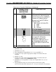
16 PC
8
DB15HD female;
RGB(VGA) input;
Formats: RGBHV, RGBS,
RGsB;
Input impedance: 75 Ω
H sync impedance: 1 kΩ
V sync impedance: 2.2 kΩ
Maximum input: level: 1 V
p-p
Maximum sync level: 5 V
p-p
Signal sensing on H sync only
17 Y PB PR LED
3
(1) Red LED, indicates a signal
at the COMPONENT input
(Continued on following page)
18 • Wall Plate Media & Computer Centers Operations & Installation Guide – DOC. 6237C