
Installation guide


Crestron QM-WMC/WMC-VCC/WCC-2 Media & Computer Centers
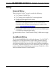
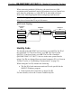
When connecting multiple QM devices, the route between a QM
origination point (transmitter) and a QM endpoint (receiver) cannot have
more than two midpoints (e.g. QM-MD7x2 or other QM switchers).
Refer to the following diagram when configuring a QM network.
NOTE: The aggregate length from transmitter to receiver cannot have a
delay skew of more than 22 ns per 100 meters.
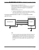
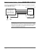
QM Network Topology
TPS-12G/15G-QM-L
QM-WMC
QM
QM
QM
QM
QM
Origination
Points
Endpoints
QM
Midpoints
QM-WMC-VCC
QM-MD7x2
QM-MD7x2
QM-WCC-2
TPS-12G/15G-QM-L
Identity Code
The Net ID of the QM-WMC has been factory set to 04. The Net ID of
the QM-WMC-VCC has been factory set to 8F. The Net ID of the
QM-WCC-2 has been factory set to 8E. The Net IDs of multiple
QM-WMC/WMC-VCC/WCC-2 devices in the same system must be
unique. Net IDs are changed from a personal computer (PC) via Crestron
Toolbox™ (refer to “Establishing Communication” on page 34).
When setting the Net ID, consider the following:
• The Net ID of each unit must match an ID code specified in the
SIMPL™ Windows program.
• Each network device must have a unique Net ID.
For more details, refer to the Crestron Toolbox help file.
Operations & Installation Guide – DOC. 6237C Wall Plate Media & Computer Centers • 23