Crestron QM-FTMC QuickMedia™ FlipTop Media Center Operations & Installation Guide
This document was prepared and written by the Technical Documentation department at: Crestron Electronics, Inc. 15 Volvo Drive Rockleigh, NJ 07647 1-888-CRESTRON All brand names, product names and trademarks are the property of their respective owners. ©2007 Crestron Electronics, Inc.
Crestron QM-FTMC FlipTop Media Center Contents QuickMedia™ FlipTop Media Center: QM-FTMC 1 Introduction ............................................................................................................................... 1 Features and Functions ................................................................................................ 1 Internal Block Diagram ............................................................................................... 4 Specifications ................
Crestron QM-FTMC FlipTop Media Center QuickMedia™ FlipTop Media Center: QM-FTMC Introduction Features and Functions The QM-FTMC FlipTop Media Center is part of the Crestron MediaManager™ line of network devices, room control systems and signal routing solutions. It is available in six different models.
FlipTop Media Center Crestron QM-FTMC Features and Functions (Continued) • • • • • • • • One RJ-45 Ethernet pass through connector One AC power pass through Two mic inputs with phantom power (on the bottom) One QuickMedia™ RJ-45 connector (on the bottom) Two Cresnet® connectors (on the bottom) Low-cost, quick and easy installation Easy setup using Crestron SystemBuilder™ software Optional cable management kit * As an option, custom-engraved buttons can be designed and obtained by using the Crestron Engr
Crestron QM-FTMC FlipTop Media Center QuickMedia dramatically simplifies system design and installation, affording a higher level of performance at a lower overall cost. NOTE: For QuickMedia wiring use CresCAT-QM, CresCAT-IM or quality Cat5e/CAT6 cable. The maximum aggregate cable length and delay skew between any QM transmitter (origination point) and QM receiver (endpoint) is 450 feet (137 meters) and 22 ns.
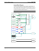
FlipTop Media Center Crestron QM-FTMC Internal Block Diagram The following diagram represents the interfacing abilities of the QM-FTMC. This Cresnet device uses QuickMedia technology to facilitate simplified connection of audio, video and computer equipment. All media and control signals are routed via a single QuickMedia cable for easy installation.
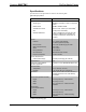
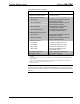
Crestron QM-FTMC FlipTop Media Center Specifications Specifications for the QM-FTMC are listed in the following table.
FlipTop Media Center Crestron QM-FTMC QM-FTMC Specifications (Continued) SPECIFICATION DETAILS Weight (Domestic Models) 4.05 lbs (1.84 kg) Weight (International Models) 4.80 lbs (2.
Crestron QM-FTMC FlipTop Media Center Physical Description This section provides information on the connections, controls and indicators available on your QM-FTMC. Refer to the physical views shown below. QM-FTMC Physical View (Top Open) QM-FTMC Overall Dimensions (Top View) 8.50 in (21.58 cm) 6.75 in (17.14 cm) 6.83 in (17.34 cm) 5.08 in (12.89 cm) 5.71 in (14.50 cm) Operations & Installation Guide – DOC. 6311B QMI-FTMC Overall Dimensions (Top View) 6.67 in (16.
FlipTop Media Center Crestron QM-FTMC QM-FTMC-NB (Top View) NOTE: The physical dimensions of the NB models are identical to the models with keypad. QM-FTMC Overall Dimensions (Front View) 5.22 in 13.24 cm 6.25 in 15.87 cm 8 • FlipTop Data Center: QM-FTMC QMI-FTMC Overall Dimensions (Front View) 7.05 in 17.90 cm 8.00 in 20.31 cm Operations & Installation Guide – DOC.
Crestron QM-FTMC FlipTop Media Center QM-FTMC (Bottom View) QMI-FTMC (Bottom View) QM-FTMC Overall Dimensions (Rear View) QMI-FTMC Overall Dimensions (Rear View) 2.32 in (5.88 cm) 2.99 in (7.60 cm) 4.32 in (10.96 cm) 4.58 in (11.61 cm) 5.39 in (13.69 cm) Operations & Installation Guide – DOC. 6311B 5.58 in (14.
FlipTop Media Center Crestron QM-FTMC QM-FTMC Overall Dimensions (Side View) QMI-FTMC Overall Dimensions (Side View) 5.51 in 14.00 cm 6.17 in 15.68 cm 4.64 in 11.77 cm 5.21 in 13.23 cm QM-FTMC Connectors, Controls & Indicators (Top View) QM-FTMC Connectors, Controls & Indicators (Bottom View) 1 2 4 3 5 6 7 10 • FlipTop Data Center: QM-FTMC 8 9 10 11 12 13 14 15 16 17 Operations & Installation Guide – DOC.
Crestron QM-FTMC FlipTop Media Center Connectors, Controls & Indicators # CONNECTORS1, CONTROLS & INDICATORS DESCRIPTION 1 KEYPAD2 Programmable keypad allowing variable combinations of large and small engravable buttons, 10 minimum (all large) to 20 maximum (all small); ships with 10 large buttons (small buttons and engraving sold separately) (1) red LED per button, programmable 2 PWR LED2 (1) green LED, indicates 24 Volts DC power supplied from Cresnet control network 3 NET LED2 (1) yellow LED
FlipTop Media Center Crestron QM-FTMC Connectors, Controls & Indicators (Continued) # CONNECTORS1, CONTROLS & INDICATORS 8 COMPUTER3 Pin 1 Pin 15 Pin 6 VIDEO 9 L VIDEO R AUDIO (VIDEO) 10 LAN 8 1 DESCRIPTION (1) DB15HD female RGB(VGA)/component video4 input Formats: RGBHV, RGBS, RGsB, YPbPr Input impedance: 75 ohms H/V sync impedance: 1k ohms Maximum input level: 1 Vp-p Maximum H/V sync level 5 Vp-p Signal detection on H, Y and Gs (1) RCA female, composite video input Input impedance: 75 o
Crestron QM-FTMC FlipTop Media Center Connectors, Controls & Indicators (Continued) # CONNECTORS1, CONTROLS & INDICATORS DESCRIPTION 14 QM5 (1) 8-wire RJ-45 female, QuickMedia output port Connects to QM input port of any QuickMedia device via CresCAT-QM or CresCAT-IM cable6 1 8 MIC/LINE (1 – 2) 15 + - G - + LAN 16 8 (2) 5-pin 3.
FlipTop Media Center Crestron QM-FTMC 5. The eight-pin RJ-45 QuickMedia transport port accepts CAT5E/CAT6 carrying audio, video and microphone signals. The QM input port conforms to the 568B wiring standard. Refer to the following table for connector pinouts.
Crestron QM-FTMC FlipTop Media Center Industry Compliance This product (QM- only) is Listed to applicable UL Standards and requirements by Underwriters Laboratories Inc. (E300530) As of the date of manufacture the QM-FTMC has been tested and found to comply with specifications for CE marking and standards per EMC and Radiocommunications Compliance Labelling. NOTE: This device complies with part 15 of the FCC rules.
FlipTop Media Center Crestron QM-FTMC Setup Network Wiring When wiring the network, consider the following: • Use Crestron Certified Wire. • Use Crestron power supplies for Crestron equipment. • Provide sufficient power to the system. CAUTION: Insufficient power can lead to unpredictable results or damage to the equipment. Please use the Crestron Power Calculator to help calculate how much power is needed for the system (http://www.crestron.com/calculators).
Crestron QM-FTMC FlipTop Media Center The aggregate cable length of a signal path originating at a QM-FTMC and terminating at a QM receiver must not exceed 450 feet (137 meters). Video signals may experience a loss of quality over very long lengths of cable. This phenomenon is due to the added resistance and capacitance of longer cable lengths and is not peculiar to either Crestron and/or QuickMedia systems. To ensure sufficient bandwidth, the maximum aggregate cable length should not exceed 450 feet.
FlipTop Media Center Crestron QM-FTMC Installation NOTE: To prevent overheating, do not operate this product in an area that exceeds the environmental temperature range listed in the table of specifications. Consideration must be given if installed in a closed or multi-unit rack assembly, inside a closed desk or in a closed podium since the operating ambient temperature of these environments may be greater than the room ambient temperature.
Crestron QM-FTMC FlipTop Media Center Button Installation QM-FTCMK Cable Management Plate The QM-FTMC is shipped with a blank bottom plate. A cable management plate is available to provide a pullout cable solution for the computer input and LAN passthrough cables. The kit contains two 6-foot cables (computer and computer audio). • Order the QM-FTCMK Cable Management Kit for domestic models. • Order the QMI-FTCMK Cable Management Kit for international models.
FlipTop Media Center Crestron QM-FTMC 5. Feed all the excess cable through the opening. 6. Attach the plate using the four #4 x ¼ LG black mounting screws retained in step 1 (use the four #4 x ¼ screws included with the QMI-FTCMK). 7. Connect the cables to the appropriate connector on the front of the QM-FTMC. 8. The cables may be secured to the bottom bar using the supplied tie wraps.
Crestron QM-FTMC FlipTop Media Center NOTE: Ensure that the cables have sufficient clearance to enable smooth movement. Allow approximately 40 inches (102 cm) from the top surface of the FlipTop box. Mounting to Surface The QM-FTMC is designed to mount in a horizontal surface, such as a desk top, lectern or podium. The following diagram illustrates the required opening size to accommodate the QM-FTMC. A cutout template (4006405 or 4006874) is included.
FlipTop Media Center Crestron QM-FTMC Mounting Bracket Screw Locations 3. Install the four #10 screws in the mounting brackets (two screws per bracket). Refer to the following diagram. 4. Slide the mounting brackets over the #6-32 screws and tighten the #6-32 screws. 5. Turn the four #10 screws equally until they contact the underside of the mounting surface. NOTE: Do not over-tighten the #10 screws as this may damage the surface and/or the unit.
Crestron QM-FTMC FlipTop Media Center NOTE: Be careful not to press the buttons while closing the FlipTop, even though the buttons are disabled when the FlipTop begins to close and all pressed buttons are released. Hardware Hookup Connect the Device Make the necessary connections as called out in the illustration that follows this paragraph. Refer to “Network Wiring” on page 16 before attaching the 4-position terminal block connector. Apply power after all connections have been made.
FlipTop Media Center Crestron QM-FTMC gauge used in interconnecting cables. The ratings on the connecting unit's supply input should be considered to prevent overloading the wiring. Ground Wire Connections Proper grounding is required. Connect the ground from the QM transmitter (QM-FTMC) to earth ground. Connect the Cresnet shield at the QM-RMCRX-BA to the chassis ground provided on the QM-RMCRX-BA. The QM-RMCRX-BA chassis must also be connected to an earth ground (building steel).
Crestron QM-FTMC FlipTop Media Center Configuration Software Have a question or comment about Crestron software? Answers to frequently asked questions (FAQs) can be viewed in the Online Help section of the Crestron website. To post a question or view questions you have submitted to Crestron’s True Blue Support, log in at http://support.crestron.com. First-time users will need to establish a user account.
FlipTop Media Center Crestron QM-FTMC Configuring with SIMPL Windows NOTE: While SIMPL Windows can be used to program the QM-FTMC, it is recommended to use SystemBuilder for configuring a QuickMedia system. SIMPL Windows is Crestron’s premier software for programming Crestron control systems. It is organized into two separate but equally important “Managers”.
Crestron QM-FTMC FlipTop Media Center • Additional QM-FTMC devices are assigned different Net ID numbers as they are added. • If necessary, double click a device to open the “Device Settings” window and change the Net ID, as shown in the following figure. “QM-FTMC Device Settings” Window • Program Manager The ID code specified in the SIMPL Windows program must match the Net ID of each unit. Refer to “Identity Code” on page 17.
FlipTop Media Center Crestron QM-FTMC Example Program An example program for the QM-FTMC is available from the Crestron website (http://www.crestron.com/exampleprograms). Adjusting the QM-FTMC Microphone Inputs Once a QM-FTMC is installed and configured, settings for gain, gating level, attack time and decay time should be set using the SystemBuilder finish tab. NOTE: Crestron recommends that you use the latest software to take advantage of the most recently released features.
Crestron QM-FTMC FlipTop Media Center Visual Representation of Gating Level, Clipping Level, Attack Time and Decay Time SIGNAL LEVEL MICROPHONE INPUT SIGNAL Clipping Level Mic On Gating Level Mic Off TIME Decay Time Attack Time SIGNAL LEVEL QM OUTPUT SIGNAL Gating Level Reached Gating Level Reached Mic On Mic Off TIME Attack Time Decay Time Setting Microphone Gain The QM-FTMC provides variable gain for the microphone inputs.
FlipTop Media Center Crestron QM-FTMC 1. To adjust the input gain, set the gain and noise gate to their lowest settings. Disable the “Mute” function by removing the check from the Mute checkbox. 2. Connect a microphone and enable phantom power if required. 3. Increase the gain while providing a “normal” sound level input to the microphone. When the “Norm” indicator shows fairly consistent activity, you have reached a good signal level for the QM-FTMC.
Crestron QM-FTMC FlipTop Media Center Uploading and Upgrading Crestron recommends using the latest programming software and that each device contains the latest firmware to take advantage of the most recently released features. However, before attempting to upload or upgrade it is necessary to establish communication. Once communication has been established, files (for example, programs or firmware) can be transferred to the control system (and/or device).
FlipTop Media Center Crestron QM-FTMC Program Checks Using Crestron Toolbox, display the network device tree (Tools | Network Device Tree) to show all network devices connected to the control system. Right-click on the QM-FTMC to display actions that can be performed on the QM-FTMC. 32 • FlipTop Data Center: QM-FTMC Operations & Installation Guide – DOC.
Crestron QM-FTMC FlipTop Media Center Problem Solving Troubleshooting The following table provides corrective action for possible trouble situations. If further assistance is required, please contact a Crestron customer service representative. QM-FTMC Troubleshooting TROUBLE POSSIBLE CAUSE(S) CORRECTIVE ACTION Net ID is not correct. Verify the Net ID in Toolbox. Net ID is not set to match the Net ID specified in SIMPL Windows. Verify SIMPL Windows program for setting Net ID.
FlipTop Media Center Crestron QM-FTMC QM-FTMC Troubleshooting (Continued) TROUBLE POSSIBLE CAUSE(S) CORRECTIVE ACTION Microphone does not produce sound. Microphone requires phantom power or cannot use phantom power. Enable or disable phantom power as necessary using controls created in the SystemBuilder project. Incorrect gain, gating level, attack time or decay time settings. Adjust gain, gating level, attack time, or decay time settings as required.
Crestron QM-FTMC FlipTop Media Center chained on the run, the Cresnet power usage of each network unit to be daisychained must be added together to determine the Cresnet power usage of the entire chain. If the unit is home-run from a Crestron system power supply network port, the Cresnet power usage of that unit is the Cresnet power usage of the entire run.
FlipTop Media Center Crestron QM-FTMC You can also log onto the online help section of the Crestron website to ask questions about Crestron products. First-time users will need to establish a user account to fully benefit from all available features. Future Updates As Crestron improves functions, adds new features and extends the capabilities of the QM-FTMC, additional information may be made available as manual updates.
Crestron QM-FTMC FlipTop Media Center Appendix A: International Receptacles PART NUMBER DESCRIPTION COUNTRIES 6003287 PWR-AU-B POWER RECEPTACLE, AUSTRALIA, 250V, 10A, BLK Australia, Fiji, New Zealand, Papua New Guinea PWR-EU-B POWER RECEPTACLE, EUROPE "SCHUKO", 250V, 16A, BLK Austria, Azerbaijan, Belarus, Bosnia and Herzegovina, Brunei, Bulgaria, Burundi, Cape Verde, Chad, Croatia, Czech Republic, Egypt, Eritrea, Finland, Georgia, Germany, Greece, Greenland, GuineaBissau, Hungary, Iceland, Jordan,
FlipTop Media Center Crestron QM-FTMC Appendix B: QuickMedia Installation and Compensation Installation Notes You must pass audio through from transmitters to receivers even if you are not using the audio signal. The information required for auto-compensation is transmitted along with the audio. In addition, the QM Link signal indicates that the QM cable is connected and that an audio signal is present on the cable.
Crestron QM-FTMC FlipTop Media Center Auto Compensation with a Self-Peaking Receiver Crestron's innovative self-peaking audio circuit eliminates the need to peak the audio signal. Without self-peaking, the same peak and boost values are applied equally to the video and audio signals. When these signals travel the same path, this arrangement is satisfactory. However, when video and audio travel to a receiver from different paths, cable lengths are unequal.
FlipTop Media Center Crestron QM-FTMC Compatibility Charts Under certain circumstances, the audio and video may be acceptably peaked even though the audio and video path lengths are different. Because the audio signal is digital and more forgiving than the video signal, it may be possible to peak the video and have functioning audio. It is difficult to predict an outcome because it is dependent on the difference in cable lengths, the video rates and acceptable video quality.
Crestron QM-FTMC KEY: FlipTop Media Center = Good operation. 1. = Operation depends on video rates and if the audio and video cable lengths are closely matched. 2. = In these cases, if the audio and video (although from different sources) switch together consistently, the system will operate normally. If the audio and video switch inconsistently, operation then depends on the video rates and how closely the audio and video cable lengths match. * = Device with self-peaking.
FlipTop Media Center Crestron QM-FTMC Return and Warranty Policies Merchandise Returns / Repair Service 1. No merchandise may be returned for credit, exchange or service without prior authorization from CRESTRON. To obtain warranty service for CRESTRON products, contact an authorized CRESTRON dealer. Only authorized CRESTRON dealers may contact the factory and request an RMA (Return Merchandise Authorization) number.
Crestron QM-FTMC FlipTop Media Center This page is intentionally left blank. Operations & Installation Guide – DOC.
Crestron Electronics, Inc. 15 Volvo Drive Rockleigh, NJ 07647 Tel: 888.CRESTRON Fax: 201.767.7576 www.crestron.com Operations & Installation Guide – DOC. 6311B (2011598) 03.07 Specifications subject to change without notice.