CRESTRON Contents SmartPresenter™: SP-1 1 Scope ................................................................................................................................... 1 Overview ............................................................................................................................. 1 Description .......................................................................................................................... 2 System Description...................................
CRESTRON SmartPresenter™: SP-1 Scope The intent of this Operations Guide is two-fold. First, it is meant as a comprehensive reference for the SmartPresenter™ system (SPS or SPSL). This document provides a system description, a list of system and ancillary equipment, system setup details, and advanced features that require use of SmartPresenter software. A less detailed presentation is available in the latest revision of the Quick Guide (Doc. 5742).
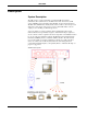
CRESTRON Description System Description The SPS system is comprised primarily of a hand-held RF user interface (transmitter), SP-1 (which serves as the RF control center and receiver), an IR sprayer (SP-MB), and programming cable (SP-CBL, used for advanced features). The SPS offers full PC mouse and keyboard control as well as control for up to four audio/video (A/V) devices such as video projectors and VCRs. There is also an output port for controlling one RS-232-type device.
CRESTRON The most recent version of the SmartPresenter software can be obtained from the Downloads page of the Crestron FTP site (www.crestron.com). System Software A Windows-based software package, SmartPresenter, is available but only necessary when performing the more advanced features of this system (i.e., configuration cloning, adding devices to the User Database, controlling a fifth device, or upgrading firmware). The software also offers the option to print a list of supported devices.
CRESTRON Physical Description of the SmartPresenter There are three SmartPresenters available: SP-1, SPI-1, and SP-1/UK. Configuration differences depend on the input power requirements and the communication frequency. The SP-1 requires a 110V external AC power pack and operates at 433.92 MHz. The SPI-1 requires a 220V external AC power pack and operates at 433.92 MHz. The SPI-1/UK requires a 220V external AC power pack and operates at 418 MHz.
CRESTRON SP-1 Ports A number of ports are provided on the back of the SP-1. Each has a silk-screened label. Refer to the illustration and descriptions below. SP-1 Ports 12 VDC .5 A (Power) This DC power socket connector is used to supply power via the Crestron external 12VDC 500 mA power pack, Crestron P/N PW-1205 or equivalent (1000 mA power pack for the SPI-1 and SP-1/UK configurations, Crestron P/N PWI-1210 or equivalent).
CRESTRON MOUSE OUT NOTE: One SmartPresenter cable, SP-CBL, for use with either a keyboard or mouse, is supplied with the SmartPresenter system. This PS/2 connector connects to the mouse port on the PC via the supplied cable, SP-CBL. Make this connection only if PC is to be controlled. KEYBOARD IN This PS/2 connector connects to any PS/2-styled keyboard; offers optional passthrough capability.
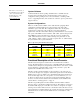
CRESTRON RF This LED illuminates when the SP-1 receives RF transmissions from a transmitter (CNWM or CNMWL) with a matching RF ID. Refer to “Match Transmitter ID to SP-1” on page 10 for details. OUTPUT (1 - 4) These LEDs illuminate or blink for a number of reasons: to indicate which output device is selected, during RF diagnostics, during device setup and verification, and while verifying routing. Leading Specifications The table below provides a summary of leading specifications for the SP-1.
CRESTRON Setup SPS Equipment Due to variations in installation requirements and overall application, not all possible peripheral pieces of equipment are supplied with the SPS system. The table below provides a list of equipment that can be used within the SPS system.
CRESTRON hardware setup is required. Due to the multiple applications, an overall hookup diagram is presented after this paragraph. Not every connection is required. Complete the following hardware hookup procedure in the order presented. Possible Hookup Connections for the SP-1 1. Attach antenna to SP-1 using right angle adapter. 2. Disconnect power to the PC (only if PC mouse/keyboard is used). 3. Attach all necessary PC cables to PC and SP-1 (only if PC mouse/keyboard is used). 4.
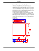
CRESTRON Match Transmitter ID to SP-1 Communication between the SP-1 and the transmitter is established via the RF ID of the transmitter. This ID can be transmitted to the SP-1 to ensure that the SP-1 recognizes a given mouse. Notice the location of the position A button on the transmitter and complete the following procedure. Location of Position A Button on Transmitter 1. Test if the RF ID matches by depressing (position A) button on the transmitter.
CRESTRON Possible RF ID Alternatives The most recent version of the SmartPresenter software can be obtained from the Downloads page of the Crestron FTP site (www.crestron.com).
CRESTRON Assignment The most recent version of the SmartPresenter software can be obtained from the Downloads page of the Crestron FTP site (www.crestron.com). 1. Depress (with a blunt object e.g., paper clip) recessed button on SP-1 that is associated with a particular device output. Observe that the red device output LED associated with the output flashes. 2. Use the device buttons (numbered 1 through 4) on the transmitter to enter the desired six digit Q-Code.
CRESTRON each output. The final step of the procedure is to save the routing settings. Complete the following procedure to selectively route IR commands to the SP-1 outputs. 1. Depress (with a blunt object e.g., paper clip) the recessed button (labeled 1) on the SP-1. Observe flashing red device output #1 LED. 2. Depress the recessed button (labeled 2) on the SP-1. Observe which device output LEDs flash red.
CRESTRON NOTE: Crestron recommends that the “linked” device be either a video projector or switcher. For example, if a VCR (assigned to button 1) is required to select the Video1 input on a projector (assigned to button 4), it is necessary to link device 1 to device 4 to make the macro function automatically. 1. Assign a valid Q-Code to output device 4. 2. Verify by selecting device 4 and pressing the device control buttons, until the correct image is displayed.
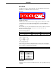
CRESTRON Controlling a PC (Mouse and/or Keyboard) The mouse and/or keyboard of a PC can be controlled via the SP-1 ports labeled MOUSE OUT and KEYBOARD OUT, respectively (refer to the illustration after this paragraph). Assign the appropriate Q-Code as defined in “Q-Code Assignment” on page 11 (i.e., the Q-Code to control all MS compatible mice is 111133). For other mice or keyboard Q-Codes, refer to the Crestron Q-Code list in the latest revision of the SmartPresenter Quick Guide (Doc. 5742).
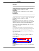
CRESTRON Controlling a Fifth (Non-IR) Device Controlling a fifth (non-IR device is an advanced feature of the SmartPresenter which requires the Windows-based SmartPresenter software. A fifth device can be controlled via the SP-1 port labeled PC (refer to the illustration below). Crestron recommends that the fifth device communicate via RS-232 and either be a switcher or video projector.
CRESTRON Problem Solving Troubleshooting The table that follows this paragraph provides corrective action for possible trouble situations. If further assistance is required, please contact a Crestron technical support representative. SP-1 Troubleshooting TROUBLE POSSIBLE CAUSE(S) CORRECTIVE ACTION Intermittent device response during transmission. Batteries in transmitter Install new batteries. are weak. SP-1 has been moved.
CRESTRON Return and Warranty Policies Merchandise Returns / Repair Service 1. No merchandise may be returned for credit, exchange, or service without prior authorization from CRESTRON. To obtain warranty service for CRESTRON products, contact the factory and request an RMA (Return Merchandise Authorization) number. Enclose a note specifying the nature of the problem, name and phone number of contact person, RMA number, and return address. 2.