CRESTRON Contents Lutron Interface 1 Description................................................................................................................................. 1 Functional Description ................................................................................................ 1 Physical Description.................................................................................................... 1 Leading Specifications..............................................................
CRESTRON Lutron Interface Description Functional Description There are two CRESTRON Lutron Interface configurations available: ST-LT and STI-LT. Configuration differences depend on which power pack is supplied. The ST-LT includes a power pack for a 120V AC supply and the STI-LT includes a power pack for 220V AC. For purposes of this Operations Guide, the term ST-LT is used for either configuration.
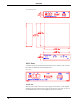
CRESTRON ST-LT Physical Views ST-LT Ports A number of ports are provided on the back of the ST-LT. Each has a silk-screened label. Refer to illustration and descriptions below. ST-LT Ports 12 VDC .5 A This DC power socket connector is used to supply external power via the supplied 500 mA power pack (1000 mA power pack for the STI-LT). If the ST-LT is part of the CRESNET II System, use of the supplied power pack is optional. 2 • Lutron Interface Operations Guide - Doc.
CRESTRON NET These two 6-pin, 6-position RJ11 modular jacks are used to connect the ST-LT module to either the SmarTouch STS or CRESNET II remote control system. When the module is part of the CRESNET II system, power is provided via the NET connection; the supplied power pack need not be attached. Two NET ports are available so that network units can be daisy-chained together. Review the latest revision of the Network Modular Cable Requirements (Doc. 5682).
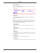
CRESTRON ST-LT Indicators There are seven LED indicators located on the front panel of the ST-LT. Refer to illustration and descriptions below. ST-LT Indicators PWR (Power) This LED illuminates when 12 volts (from power packs) or 24 volts DC (from network) is supplied to the ST-LT. NET This LED remains illuminated when communication between either the SmarTouch STS or CRESNET II remote control system and the ST-LT is established.
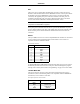
CRESTRON Leading Specifications The table below provides a summary of leading specifications for the ST-LT module. Dimensions and weight are approximations rounded to the nearest thousandth unit. Leading Specifications of the ST-LT SPECIFICATION Power Requirements Power Factor CRESNET II Workshop SIMPL Compiler CRESNET II Operating System SmarTouch Operating System STS VisionToolsTM for Windows (STS/VTW) STS Database Dimensions & Weight DETAILS 12 or 24 VDC 2.5 Watts Version 5.24 or later 3.18.
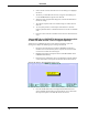
CRESTRON 4. Notice the list of current network devices in the dialog box. Highlight the ST-LT. 5. The factory set NET ID of the ST-LT (1C) appears in the dialog box. Use the scroll arrow to assign the new NET ID. 6. When the newly assigned NET ID appears, select the Set ID button to initiate the change. 7. The software responds with a successful message to confirm the new NET ID. 8. To verify this procedure, select Report Network Devices from the Options pull-down menu.
CRESTRON Changing the NET ID - ST-LT Workshop Screens (2 of 3) 5. Enter a new NET ID code (in two-digit hexadecimal format) and depress ENTER. The Workshop responds with the screen shown below that displays a message stating the “New ID” command has been sent. Changing the NET ID - ST-LT Workshop Screens (3 of 3) 6. To verify this procedure, depress F4 to perform a network poll. Confirm that the ST-LT has the new NET ID code. 7.
CRESTRON 4. Slide the top cover toward the back panel while holding the ST-LT in place until the cover is free. 5. Locate the dip switch and notice the orientation (#1 - #8); refer to illustration below. Location of Dip Switch on ST-LT PC Board ST-LT PORTS DETAIL OF 8-POSITION DIP SWITCH SW2 ON 1 2 3 4 5 6 7 8 ST-LT LEDS 6. Refer to the table below for the dip switch settings for your particular application.
CRESTRON Preparation for Use Refer to the two hookup diagrams below. The first diagram illustrates the connections to SmarTouch STS. The second diagram shows connections to the CRESNET II system. Other than making the power connection last, complete the connections in any order, regardless of whether the ST-LT is part of SmarTouch STS or the CRESNET II system. NOTE: Refer to the latest revision of the CRESTRON Network Modular Cable Requirements (Doc. 5682) when making connections to the port labeled NET.
CRESTRON Programming Using STS/VTW Software NOTE: The following description assumes that the reader has some knowledge of STS/VTW software. If not, please refer to the SmarTouch Tutorial that is available from the STS/VTW Help menu. Use STS/VTW software (version 10.7 or higher and STS database version 10.7.100.02 or later) to include the ST-LT in lieu of a Lutron GRAFIK Eye device into a SmarTouch system. Once included, a command sequence or macro must be enabled via software.
CRESTRON Select Open and Project from the File menu to open the touchpanel project file. For this sample, the project has been named LUTRON.PRJ. This lighting page, shown below, was taken from the VTW Template subdirectory, TST1500C.PRJ, page name LIGHT-LUTRON-GEYERS232. 5. Open or create a lighting page with associated buttons. The STS Wizard uses template projects, many of which offer typical lighting pages. One such page is shown below.
CRESTRON The macro in this sample shall address MAIN-UNIT-2 and select ZONE-1-UP. 8. A macro is created by adding the appropriate commands and delays as required. Click the Insert Command button to open the “Device Functions” dialog box. 8. Highlight the ST-LT in the Device area to display the associated functions in the right-hand column. 9. Select MAIN-UNIT-2 as the desired function. The dialog box should appear as shown below; click OK. Device Functions Dialog Box 11.
CRESTRON SIMPL SIMPL is CRESTRON’s programming language designed for easy implementation of the control system requirements. The best representation of SIMPL programming is the block diagram. A basic ST-LT SIMPL program is shown and described below. ST-LT SIMPL Program CT-1500 ST-COM UNIT1-SCENE2 1 :A21 UNIT7+8-SCENE16 2 :AG78 UNIT3-ZONE1- 3 4 :D31 MV 0 TRIG OUT STOP-DOWN-ALL :E [TRIG*] 0.1s S-# UNIT3-ZONE1+ :B31 MV 0 TRIG OUT STOP-UP-ALL :C [TRIG*] NET.ID:03 0.1s S-# NET.
CRESTRON ST-LT Workshop Screens (2 of 4) ST-LT Workshop Screens (3 of 4) ST-LT Workshop Screens (4 of 4) The ST-LT is defined as an “ST-COM, Port A”. Enter “GRAFIK” into the baud rate field to allow the ST-LT to communicate with the Grafik Eye unit. The fields for parity, data bits, and stop bits are not used and may be set to any value. If Port B is defined to be 9600 N81, a RS-232 link to the Grafik Eye unit through the RS-232 port on the back of the ST-LT is permitted.
CRESTRON The data field contains the command protocol for the Grafik Eye system. A description of commands, their operation, and examples are provided in the table below.
CRESTRON Problem Solving Troubleshooting The table below provides corrective action for possible trouble situations. If further assistance is required, please contact a CRESTRON technical support representative. ST-LT Troubleshooting TROUBLE POSSIBLE CAUSE(S) CORRECTIVE ACTION PWR LED does not illuminate. ST-LT is not receiving power. NET LED does not illuminate. Improper NET ID. LUTRON PWR LED does not illuminate. Loose network connection. Lutron Mux Link Network is not receiving power.
CRESTRON Return and Warranty Policies Merchandise Returns / Repair Service 1. No merchandise may be returned for credit, exchange, or service without prior authorization from CRESTRON. To obtain warranty service for CRESTRON products, contact the factory and request an RMA (Return Merchandise Authorization) number. Enclose a note specifying the nature of the problem, name and phone number of contact person, RMA number, and return address. 2.
CRESTRON Appendix: GRAFIK Eye Commands NOTE: This entire appendix is a reprint of Lutron’s technical reference material. Format for Commands The RS-232 interface is commanded by ASCII strings in the following format. : A 1 2 3 ... Command Clear Parameters Input Buffer Command Carriage Return Notice that capital letters must be used for commands and there are no spaces between characters. To execute more than one command, enter a space instead of the carriage return and enter the next command.
CRESTRON Examples: :A21 :AG45 A78 :A0123 A145 A38 Select scene 2 on GRAFIK Eye Main Unit 1. Select scene 16 on GRAFIK Eye Main Units 4 and 5; select scene 7 on GRAFIK Eye Main Unit 8. Turn off GRAFIK Eye Main Units 1, 2 and 3; select scene 1 on GRAFIK Eye Main Units 4 and 5; select scene 3 on GRAFIK Eye Main Unit 8. (SL) Scene Lock When a GRAFIK Eye Main Unit is selected by this command, it is locked in the current scene and does not allow lighting changes.
CRESTRON Example of Response: ~:ss2L0MAR95 1 OK Main Unit A1 is in scene 2 Main Unit A2 is sending a master lower Main Unit A3 is OFF Main Unit A4 is missing Main Unit A5 is in scene 10 Main Unit A6 is sending a master raise Main Unit A7 is in scene 9 Main Unit A8 is in scene 5 (SQ) Sequence This command determines which GRAFIK Eye Main Units are sequenced (changed from scene to scene with fade times set by GRAFIK Eye Main Units).
CRESTRON (D) Zone Lower This command causes the zones of the selected GRAFIK Eye Main Units to gradually decrease in intensity. The first parameter is the GRAFIK Eye Main Unit and the second is the zone(s) affected. Any zone numbers not listed are unaffected. If the command is given for a GRAFIK Eye Main Unit and no zones are listed, zones that are currently ramping down on that Main Unit stop. Invalid GRAFIK Eye numbers return an error statement.
CRESTRON Examples: :C Stop all zones on all GRAFIK Eye Main Units that are ramping up. Stop all zones that are being raised or lowered. :C E GRX-AV-RS232/ATC Command List The following set of commands can be used only with the GRX-AV-RS232/ATC. (ST) Set Time This command sets the internal timeclock to the given time and date. The seconds are reset to 00 when the command is issued. Notice that the timeclock can be set directly through Lutron’s GRAFIK Eye Timeclock software.
CRESTRON 0 = no schedule active 1 = "weekday" schedule 2 = "weekend" schedule 3 = "special 1" schedule 4 = "special 2" schedule Any other value causes no schedule to be run. Examples: :SS 4 :SS 0 Start special schedule 4. Stop timeclock from executing events. (RS) Report Schedule This command tells the unit to report the schedule that it is currently running. If this command is used on a GRX-AV-RS232 unit, an error condition is issued. Example: :RS Report schedule .
CRESTRON Example: :QS Start super sequence . (QP) Super Sequence Pause This command stops the preprogrammed super sequence that is running at its current step. If a super sequence is not running, the command does nothing. If a super sequence has not been loaded using the GRAFIK Eye Timeclock software, an error statement is reported. The sequence can be restarted from this point by a super sequence resume command. Example: :QP Stop super sequence at the current step.
CRESTRON This page intentionally left blank. Operations Guide - Doc.
CRESTRON This page intentionally left blank. 26 • Lutron Interface Operations Guide - Doc.
CRESTRON This page intentionally left blank. Operations Guide - Doc.