
Specifications


CRESTRON
NET
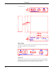
These two 6-pin, 6-position RJ11 modular jacks are used to connect the ST-LT
module to either the SmarTouch STS or CRESNET II remote control system. When
the module is part of the CRESNET II system, power is provided via the NET
connection; the supplied power pack need not be attached. Two NET ports are
available so that network units can be daisy-chained together. Review the latest
revision of the Network Modular Cable Requirements (Doc. 5682).
NOTE: Most 4-conductor phone cables are wired in a crisscross fashion and are not
compatible with CRESTRON equipment.
If the power pack is attached when the ST-LT is part of the CRESNET II system,
power is drawn from the power pack. The module does not load the network power,
but the network power remains chained for additional network devices that are
connected.
RS-232
This 9-pin (DB9) connector is a Lutron compatible RS-232 interface for connections
to a PC running Lutron configuration and control software. This connector is
equivalent to Lutron’s GRX-AV-RS232.
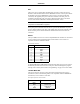
ST-LT Pinout (RS-232)
PIN DESCRIPTION
1
n/c
2
TXD
3
RXD
4
n/c
5
GND
6
n/c
7
CTS
8
RTS
9
n/c
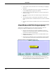
A standard DB9 male to DB9 female straight-through cable may be used to connect
the RS-232 port of the ST-LT to a PC. This port is activated through the program
running on the control system. Refer to “Programming” on page 10 for more details.
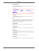
LUTRON MUX LINK
This 4-pin connector connects to the Lutron Mux Link Network. The Lutron’s
network line (refer to the following table) is not compatible with the CRESTRON
network line; do not connect to each other.
Description of Lutron Network Lines
LUTRON DESCRIPTION
MUX*
DATA- Line
MUX
DATA+ Line
+V
Voltage Line
COM
Ground
Operations Guide - Doc. 5694 Lutron Interface • 3