Crestron STX-1700CXP 2-Way RF Wireless Touchpanel Operations Guide
This document was prepared and written by the Technical Documentation department at: Crestron Electronics, Inc. 15 Volvo Drive Rockleigh, NJ 07647 1-888-CRESTRON All brand names, product names and trademarks are the property of their respective owners. ©2004 Crestron Electronics, Inc.
Crestron STX-1700CXP 2-Way RF Wireless Touchpanel Contents 2-Way RF Wireless Touchpanel: STX-1700CXP 1 Introduction ............................................................................................................................... 1 Functions and Features ................................................................................................ 1 Specifications ..............................................................................................................
Crestron STX-1700CXP 2-Way RF Wireless Touchpanel 2-Way RF Wireless Touchpanel: STX-1700CXP Introduction Functions and Features The STX-1700CXP is a two-way wireless radio frequency (RF) compact color touchpanel that utilizes 2.4 GHz spread spectrum technology to provide a user interface to a Crestron® control system (Cresnet® system). The “Wi-Fi friendly” touchpanel is a handheld transceiver that communicates through Crestron’s gateway/transceiver, the TPS-RFGWX (sold separately), to the Cresnet system.
2-Way RF Wireless Touchpanel Crestron STX-1700CXP Included with the STX-1700CXP are a Crestron High Performance Rechargeable Battery Pack (ST-BTPN) and a Docking Station (ST-DSN) that docks the touchpanel and/or recharges the ST-BTPN. An external power pack (PW-1215 for domestic use or PWI-1215 for international use) is also provided to power the touchpanel. Refer to the latest revisions of the documentation supplied with these items for details.
Crestron STX-1700CXP 2-Way RF Wireless Touchpanel 802.11b-compliant RF devices, it is important to bear in mind how each implementation uses the frequency bandwidth, and how they may interact. The 802.11b spectrum ranges from 2400 MHz to 2497 MHz, and is divided into channels spaced at 5 MHz intervals. Each channel, though, is 22 MHz wide (±11 MHz around the center frequency), which results in some overlap between channels.
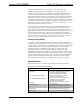
2-Way RF Wireless Touchpanel Crestron STX-1700CXP Specifications of the STX-1700CXP Touchpanel (continued) SPECIFICATION DETAILS Default RF Channel³ 01 (Identifies RF gateway to be used for communication.) Default RF Band³ Band 0 (USA Original) Ten frequency bands (ranges) available for selection.
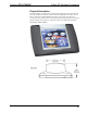
Crestron STX-1700CXP 2-Way RF Wireless Touchpanel Physical Description The touch-sensitive viewing screen is located on the front of the STX-1700CXP. The electronic hardware is housed in a black and silver molded plastic enclosure, shown below. Connectors to upload touchscreen projects via Cresnet, using a PC and Crestron processor, and to power the unit using the external power pack are located on the left and right sides of the unit, respectively. Refer to the following illustrations.
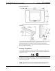
2-Way RF Wireless Touchpanel Crestron STX-1700CXP Physical Views (continued) The underside of the unit contains the battery compartment that holds one ST-BTPN. Contacts for the ST-DSN are through the ST-BTPN. Four rubber feet on the underside of the unit are for stability and to prevent slippage on flat surfaces. Refer to “Programming Cable” on page 22 for details and pinouts of the cable used for programming and uploading.
Crestron STX-1700CXP 2-Way RF Wireless Touchpanel designed to provide reasonable protection against harmful interference in a residential installation. The equipment generates, uses and can radiate radio frequency energy and, if not installed and used in accordance with the instructions, may cause harmful interference to radio communications. However, there is no guarantee that interference will not occur in a particular installation.
2-Way RF Wireless Touchpanel Crestron STX-1700CXP Net ID Every equipment and user interface wired to the Cresnet system requires a unique Net ID. These codes are two-digit hexadecimal numbers from 03 to FE. The Net ID of the unit must match the Net ID specified in the SIMPL Windows program. The Net ID is used during uploading of a Crestron VisionTools® Pro-e (VT Pro-e) project or upgrading the touchpanel firmware. The Net ID is also used when operating the unit as a wired touchpanel.
Crestron STX-1700CXP 2-Way RF Wireless Touchpanel Calibration Menu CALIBRATION MENU Calibration of the touchscreen is required if the active touch area of a button does not coincide with the button's image. Select the Touch Screen Calibration button to display the CALIBRATION MENU, as shown to the left. The CALIBRATION MENU offers the choice to initiate calibration with the Perform Calibration button or return to the previous screen with the Return button.
2-Way RF Wireless Touchpanel CRESNET INTERFACE MENU 03 Crestron STX-1700CXP Cresnet Interface Menu CRESNET ID is a two-digit hexadecimal number that can range from 03 to FE. Note that if the panel is to be used in a wired mode, this number and the Net ID set in the SIMPL Windows program of the Cresnet system must match. Net ID for the STX-1700CXP is factory set to 03. The UP and DOWN buttons increase and decrease the CRESNET ID by one digit (i.e., 03, 04, 05, . . .FE).
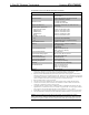
Crestron STX-1700CXP Band # 0 1 2 3 4 5 6 7 8 9 2-Way RF Wireless Touchpanel Freq. Range (MHz) 2400-2474 2448-2474 2448-2474 2471-2497 2452-2477 2400-2425 2409-2435 2419-2445 2430-2455 2440-2465 Occupied 802.
2-Way RF Wireless Touchpanel Crestron STX-1700CXP Power Management Timeout Settings POWER MANAGEMENT TIMEOUT SETTINGS 10 30 The Power Management feature is intended to conserve energy, and to extend the service life of the battery. From the SETUP MENU, press the Power Management button to display the POWER MANAGEMENT TIMEOUT SETTINGS screen. Use the STANDBY and POWER DOWN UP and DOWN buttons to set the respective timeouts from 0 through 120 minutes, where 0 disables the timeout.
Crestron STX-1700CXP 2-Way RF Wireless Touchpanel General Use and Safety WARNING: To avoid shock hazard and possible damage to the unit, do not use the touchpanel in the rain or expose it to unnecessary moisture. Recommended Touchpanel Cleaning Keep the surface of the touchscreen free of dirt, dust, or other materials that could degrade optical properties. Long-term contact with abrasive materials can scratch the surface, which may detrimentally affect image quality.
2-Way RF Wireless Touchpanel Crestron STX-1700CXP • Crestron Database version 16.2.1 or later. Required by SIMPL Windows. • VisionTools Pro-e version 3.2.1.8 or later. Used for graphical touchscreen design. • (Optional) Crestron Engraver version 2.3.0.0 (only required if using SystemBuilder or if optional hard buttons and bezel are installed, and 1700C-BTNB or 1700C-BTNS engraveable button kits are purchased).
Crestron STX-1700CXP 2-Way RF Wireless Touchpanel The System Views lower pane displays the PRO2 system tree (refer to graphic below). This tree can be expanded to display and configure the communications ports. Expanded PRO2 System Tree C2Net-Device Slot in Configuration Manager To incorporate an STX-1700CXP into the system, a gateway device is required. The C2Net-Device Slot can accept a gateway such as the TPS-RFGWX.
2-Way RF Wireless Touchpanel Crestron STX-1700CXP “Device Settings” Window for the TPS-RFGWX Similarly, expand the system tree in the lower pane and double-click the STX-1700CXP icon to open the “Device Settings” window for the touchpanel. Select the RF/IR ID tab to change the touchpanel RF ID, as shown below. For more information on setting the RF/IR ID, refer to “RF Setup” shown on page 10.
Crestron STX-1700CXP 2-Way RF Wireless Touchpanel Signal Types Signals interconnect the various devices and logic symbols that comprise a SIMPL program. Signals can be one of three types: digital, analog, or serial. For any given signal, the signal type is determined by its driving source. That is, if the symbol that drives the signal has an analog output, then, by definition, the signal connected there will be an analog signal.
2-Way RF Wireless Touchpanel Crestron STX-1700CXP Digital Output Signal Descriptions OUTPUT press 1 through press 4000 DESCRIPTION Notifies control system of button press (1 – 4000). High/1 = press On Low/0 = press Off Digital Input Signal Descriptions INPUT fb 1 through fb 4000 DESCRIPTION Notifies panel to display feedback (1 – 4000). This can represent that the button was pressed, or can be actual device feedback, e.g., that power was turned on.
Crestron STX-1700CXP 2-Way RF Wireless Touchpanel touchpanel’s flash PROM. The touchpanel uses the project until another is uploaded from the PC. The PC may be disconnected from the control processor except when uploading a project. For additional software information, refer to the help file provided with the software. The latest version of VT Pro-e can be obtained from the Crestron website.
2-Way RF Wireless Touchpanel Crestron STX-1700CXP Digital Reserved Join Numbers STX-1700CXP (continued) JOIN NUMBER 17231 FUNCTION Standby Timeout VALUE Up DIRECTION 17232 Standby Timeout Down 17233 17234 17242 17302 17303 17304 17305 17322 17323 17324 17509 Power Timeout Power Timeout Setup Keyclick Keyclick Key Click Volume Key Click Volume Key Click Short Key Click Medium Key Click Long Up Down N/A On Off Up Down Short (Default) Medium Long N/A I I I I I/O I/O I I I I I 17532 1. 2.
Crestron STX-1700CXP 2-Way RF Wireless Touchpanel NOTE: The Crestron Viewport utility performs multiple system tasks, primarily via an RS-232 or TCP/IP connection between the control system and a PC. It is used to observe system processes, upload new operating systems and firmware, change system and network parameters, and communicate with network device consoles and touchpanels, among many other tasks. Viewport can also function as a terminal emulator for generic file transfer.
2-Way RF Wireless Touchpanel Crestron STX-1700CXP NOTE: If the control system in use has a 4-pin network connector rather than a modular (RJ-11-type) NET connector, use an ST-CBL interface cable (sold separately). NOTE: To make a cable for either configuration, refer to the “Programming Cable Specifications” diagram after these notes. NOTE: An adapter such as a CN-RJ11 (sold separately) is required when using the RJ-11 cable.
Crestron STX-1700CXP 2-Way RF Wireless Touchpanel 4. Attach the appropriate Crestron external power pack to the touchpanel and plug it into an outlet. At the PC, make sure that no programs accessing the COM port of the PC are running. 5. Open the Crestron Viewport. Either launch the stand-alone version of Viewport, or start SIMPL Windows or VT Pro-e, and from the menu bar, select Tools | Viewport. 6.
2-Way RF Wireless Touchpanel Crestron STX-1700CXP “Port Settings” Window 8. Proceed to “Uploading a VT Pro-e Project” below or “Firmware Upgrade” that begins on page 25, as appropriate. Uploading a VT Pro-e Project A compiled VT Pro-e file has the extension .vtz To upload a compiled VT Pro-e project to the STX-1700CXP, complete the following steps. 1. Make sure that “Communication Settings” that begins on page 21 has been performed. 2.
Crestron STX-1700CXP 2-Way RF Wireless Touchpanel “Touchpanel Transfer” Window 4. Click Browse. The “Open” window appears as shown below. 5. Select the VT Pro-e (.vtz) file and click Open. The transfer completes automatically. Select VTZ File 6. Disconnect the programming cable and the external power pack from the touchpanel. 7. Close the Viewport, exit VT Pro-e, and disconnect the programming cable from the PC and the control system. Firmware Upgrade A firmware upgrade file has the extension .
2-Way RF Wireless Touchpanel Crestron STX-1700CXP Select Update Touchpanel Firmware 3. As shown below, select the Net ID of the STX-1700CXP and then click OK. “Select Network ID” Window 4. As shown below, select the firmware (CSF) file and click Open. The transfer will complete automatically. Select CSF File 5. Disconnect the programming cable and the external power pack from the touchpanel. 26 • 2-Way RF Wireless Touchpanel: STX-1700CXP Operations Guide - DOC.
Crestron STX-1700CXP 2-Way RF Wireless Touchpanel Problem Solving Troubleshooting The table below and continued on the next page provides corrective action for possible trouble situations. If further assistance is required, please contact a Crestron customer service representative.
2-Way RF Wireless Touchpanel Crestron STX-1700CXP STX-1700CXP Troubleshooting (continued) TROUBLE Touchpanel display is dark. Touchpanel operation appears unreliable. Touchpanel does not function and SIG LED on STRFGWX illuminates, but Rx or Tx LEDs do not. Sig LED on TPSRFGWX does not illuminate. Touchpanel screen changes without touching the screen. POSSIBLE CAUSE(S) Standby or power down timeout has elapsed. CORRECTIVE ACTION Touch screen to reactivate. No power to the touchpanel.
Crestron STX-1700CXP 2-Way RF Wireless Touchpanel You can also log onto the online help section of the Crestron website to ask questions about Crestron products. First-time users will need to establish a user account to fully benefit from all available features. Future Updates As Crestron improves functions, adds new features, and extends the capabilities of the STX-1700CXP, additional information and programming examples may be made available as manual updates.
2-Way RF Wireless Touchpanel Crestron STX-1700CXP Appendix A: Optimum RF Reception Guidelines Many factors can affect the reliability of RF communication between an RF gateway and an RF touchpanel. While an effort has been made to determine operating specifications, some specifications are not constant. RF Communication can be limited by several factors including but not limited to EMI (electromagnetic interference), intervening objects, antenna orientation and receiver placement.
Crestron STX-1700CXP 2-Way RF Wireless Touchpanel NOTE: RF propagation is best from the sides of the antenna. Horizontal Orientation Building Top of gateway Antenna Vertical Orientation Building Antenna RF GATEWAY - 2 WAY RF PW R N ET SIG ANTENNA Rx Tx CRESTRON TPS-RFGWX Front of gateway Right Angle Orientation Building Top of gateway Antenna Operations Guide – DOC.
2-Way RF Wireless Touchpanel Crestron STX-1700CXP Appendix B: Installation of Optional Pushbuttons The STX-1700CXP is supplied with ten optional pushbutton switches, blank buttons, and a bezel to accommodate the switches. As a further option, custom engraved black buttons (1700C-BTNB) or silver buttons (1700C-BTNS) can be designed and purchased via the Crestron Engraver software. Version 2.3.0.0 or later is available from the Crestron website.
Crestron STX-1700CXP 2-Way RF Wireless Touchpanel Software License Agreement This License Agreement (“Agreement”) is a legal contract between you (either an individual or a single business entity) and Crestron Electronics, Inc. (“Crestron”) for software referenced in this guide, which includes computer software and, as applicable, associated media, printed materials, and “online” or electronic documentation (the “Software”).
2-Way RF Wireless Touchpanel Crestron STX-1700CXP If You are a business or organization, You agree that upon request from Crestron or its authorized agent, You will within thirty (30) days fully document and certify that use of any and all Software at the time of the request is in conformity with Your valid licenses from Crestron of its authorized agent.
Crestron STX-1700CXP 2-Way RF Wireless Touchpanel Return and Warranty Policies Merchandise Returns / Repair Service 1. No merchandise may be returned for credit, exchange, or service without prior authorization from CRESTRON. To obtain warranty service for CRESTRON products, contact the factory and request an RMA (Return Merchandise Authorization) number. Enclose a note specifying the nature of the problem, name and phone number of contact person, RMA number, and return address. 2.
Crestron Electronics, Inc. 15 Volvo Drive Rockleigh, NJ 07647 Tel: 888.CRESTRON Fax: 201.767.7576 www.crestron.com Operations Guide - DOC. 6227A 12.04 Specifications subject to change without notice.