DCS 6000 User Manual Digital Conference System CU 6005/6010/6011 Central Unit Central Unit for series DCS 6000 Voting Units, Conference Units, Interpreter Units, Ambient Noise Microphone, Channels Selectors and Audio Output Units Danish Interpretation Systems DIS
Danish Interpretation Systems Copyright © 2007 DIS User Manual CU6005 6010 6011 REV V.DOC 16-07-2007 No part of this publication may be reproduced or utilised in any form or by any means without permission in writing from the publisher.
Danish Interpretation Systems User Manual List of Contents List of Contents..................................................... 3 System settings ..............................................23 Important .............................................................. 5 Normal Operation ..........................................23 Compliancy........................................................ 5 System Setup........................................................24 Important safety instructions..
Danish Interpretation Systems User Manual Microphone conference system with 3+1 ch. interpretation & IR, CU 6005........................ 32 Microphone conference system with 15+1 ch. interpretation & IR, CU 6010........................ 32 Various configurations with RP 6004 Repeater and PS 6000 Power Supply ........................... 33 Appendix ..............................................................36 Technical appendix..........................................36 Cabling.........................
Danish Interpretation Systems User Manual Important The equipment must be connected to earth Compliancy The equipment has been tested and found to comply with the limits of the following standards for digital devices: • • • • • EN55103-1 (Emission) EN55103-2 (Immunity) EN60065 safety UL6500 safety FCC rules part 15, class A (Emission) Warning – To reduce the risk of fire or electric shock, do not expose this apparatus to rain or moisture.
Danish Interpretation Systems User Manual To avoid moisture condensations do not install the unit where the temperature may rise rapidly. Warranty When installing the unit inside a 19” rack, observe that the rack is properly ventilated. The maximum allowed temperature inside the rack is 40 °C. The unit is minimum covered by 12 months warranty against defects in materials or workmanship. Cleaning & Repacking To keep the cabinet in its original condition, periodically clean it with a soft cloth.
Danish Interpretation Systems User Manual Description of the DCS 6000 system • Features The DCS 6000 system has the following main features: Added functionality and comprehensive features provided by SW 6000 software package running on PC RS232/RS422 connection on CU 6005/6010/6011 for external operation of the system of a PC or control system such as AMX or Crestron • Fully digital • Excellent sound quality • “State of the Art” fully digital integrated interpretation, discussion and voting system
Danish Interpretation Systems User Manual System components Conference equipment and channel selectors The CU 6005/6010/6011 Central Unit supports all available units in the DCS 6000 series: CS 6032F V/H DC 6990P Central equipment etc.
Danish Interpretation Systems User Manual Operating instructions • Delayed switching on of power to the four chains, to minimise the total ‘in-rush’ current on the Mains supply. General description • Designed in a standard 2HE 19” cabinet. The CU 6010 Central Unit for the DCS 6000 is the heart of the system. One CU 6010 is needed in each DCS 6000 system. The CU 6010 consist of four main parts: • Functionality on the CU 6010 depends on the Feature License uploaded into the unit.
Danish Interpretation Systems User Manual User Controls, indications & connectors Front plate layout The front plate layout of the CU 6010 Central Unit consists of a large illuminated LCD display and 8 buttons for setting up/controlling the system: Details of display -Audio Control -Delegate setup -Interpreter setup -Units info MENU Front plate controls The CU 6010 Central unit features the following controls and display: Power switch Switches power on to the whole system.
Danish Interpretation Systems User Manual Buttons The buttons below and to the left of the display are used when stepping through the different menus and for setting up the system: • Enter button The Enter button is used, when a selection is made in the Main Menu. Pressing the Enter button concludes the selection made, and at the same time it indicates a confirmation of the possible changes made within the selection. The Menu system returns to the previous menu.
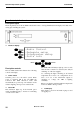
Danish Interpretation Systems User Manual Back Panel Layout Interpreter sets for those languages have to be connected to Chain B1 or B2. Back Panel Connectors Mains Power connector Connection for mains power. See specs. Chain B1 & B2 RJ45 connector, 2 pieces Analog Audio Line input XLR Input connector. For connection of external Line input signal i.e. the Floor (Speaker) signal from another Conference Microphone System or audio mixers. See specs. Analog Audio Line output.
Danish Interpretation Systems User Manual A selection is made in the Main menu by scrolling through the menu items with the Up/Down buttons, and pressing the Select button associated with the desired menu item. When scrolling through the menu items, the Main menu wraps around the list of menu items, i.e. passing the last menu item makes the first menu item appear, and likewise when passing the first menu item. Pressing the Menu and Enter buttons does not have any effect in the Main Menu.
Danish Interpretation Systems User Manual Values: {Auto, Manual, FIFO, VOX}: Delegate setup The “Delegate setup” following entries: • • • • • menu comprises the • Max Speakers Max. Requests Operation Mode Voice Detection Auto Off Setup This is indicated by a red light in the ‘Speak’ lamp in the microphone unit. Pressing the microphone ON/OFF button again will turn the microphone off Max Speakers A Chairman Unit is always in Auto or VOX mode. This menu point has two settings: • • • Max.
Danish Interpretation Systems User Manual More delegates will be put in the request queue when they press their ON/OFF buttons, until the maximum of requests is reached. Their green ‘Request’ lamps will light up steadily. When one of the turned ON microphone units is switched off, the first delegate unit in the queue is automatically switched ON, and the next delegate unit in the queue will flash with the green ‘Request’ lamp. This mode will normally be used with only 1 as maximum speakers.
Danish Interpretation Systems User Manual This setting is used to set the time from the delegate stops talking until the microphone turns off. The default value is 4 sec. Channel 0 will always give the original audio (floor). Auto Off Setup This menu point has two settings: • • Auto Off Auto Off time Those settings determine the behaviour of the Auto Off facility for the conference units. • When set to 0 value no interpretation channels are present in the system.
Danish Interpretation Systems • User Manual Complete Lock With this setting an interpreter cannot switch on his microphone to any occupied interpreter channel. This is the default setting. • No Lock With this setting an interpreter turning on his microphone to any occupied interpreter channel, will turn of the interpreter occupying the channel. • Transmission of ambient noise rather than transmitting no sound at all is a desirable feature from listeners attending the meeting via headphones.
Danish Interpretation Systems User Manual The Chain info menu displays information to the user about units connected to the CU. The information is divided into Chain A, Chain B and total. Found units are connected units, where the communication is maintained, and expected units comprises all units, which are defined in the ‘Configuration’. Display Unit types Selecting the Display Unit types in the Units info menu displays the number of present units.
Danish Interpretation Systems User Manual The load is aborted with the Menu button and accepted with the Enter button. In both cases, the menu system returns to the Main menu. When switching the power to the CU 6010 OFF and then ON, the last saved setting will also be loaded.
Danish Interpretation Systems User Manual The user returns to the main menu by pressing either the Menu button or the Enter button. This screen is the standard screen showed at normal use. This screen is automatically shown if no buttons is pressed in 2 minutes. The function of this screen is explained in the section Audio Control menu. Normal Operation Powering up Use with SW 6000 Switch on power at the CU 6010.
Danish Interpretation Systems User Manual The LinelnLevel Adj has to be set as high as possible for maintaining the best S/N ration, but not too high to avoid clipping, whereas the LineIn- >LoudSpk is used for setting the audio level needed in the loudspeakers.
Danish Interpretation Systems User Manual • Controls up to max. 500 Conference/Voting units. Controls of Interpreter Sets or other controllable units are as for CU 6010. General description • The functionality of CU 6005 is basically identical to the CU 6010 Central Unit; however the main parts are slightly different: Designed for up to 16 interpreted channels (instead of 31) and 8 open microphones • Built in Power Supply for app 50 Conference Units (instead of 200) or app.
Danish Interpretation Systems User Manual User Controls, indications & connectors Front plate layout Identical to the CU 6010 Central Unit. Front plate controls Identical to the CU 6010 Central Unit. Back Panel Layout Back Panel Connectors As the CU 6010 Central Unit with the following differences: Chain A1 & A2 (no chain B1 & B2) System settings The same as for the CU 6010 Central Unit.
Danish Interpretation Systems User Manual System Setup General guidelines Connect the CU 6005/6010/6011 to the various DCS 6000 units using Cat5 or Cat5e FTP or STP screened cables. The operation of the DCS 6000 units is found in the User Manual for the specific units. between the units. Please consult the next section ‘Maximum number of units to be connected’. • The maximum number of languages configured on chain A (A1 or A2) or B (B1 or B2) is 16.
Danish Interpretation Systems User Manual Maximum number of units to be connected The following table shows the maximum number of units, which can be connected to each of the four outputs (A1, A2, B1 or B2) on a CU 6010/6011 Central Unit or on each output on an EX 6010 Extension Unit or on the output of a PS 6000.. CM/DM 60x0P Chairman/Delegate Units – CU 6010/6011 Length of Feeding Cable Type CAT5 AWG24 Length of inter connecting Cable, Type CAT5 AWG24 Total cable length Max.
Danish Interpretation Systems User Manual Length of Feeding Cable, Type CAT5 AWG24 Length of Cable between each JB 6002, Type CAT5 AWG24 Total cable length Number of JB 6002 Max.
Danish Interpretation Systems User Manual DC 6990P Conference Units – CU 6010/6011 The following table shows the maximum number of units, which can be connected to each of the four outputs (A1, A2, B1 or B2) on a CU 6010/6011 Central Unit or on each output on an EX 6010 Extension Unit or on the output of a PS 6000. Length of Feeding Cable Type CAT5 AWG24 Length of inter connecting Cable, Type CAT5 AWG24 Total cable length Max.
Danish Interpretation Systems User Manual MU 6040C/D and MU 6042D without connected loudspeaker – CU 6010/6011 The numbers are valid with no audio in loudspeaker (no loudspeaker connected to each unit). If loudspeakers are used, then use the figures for CM/DM 60x0P above.
Danish Interpretation Systems User Manual IS 6132P w/JB 6004 and LS 6032 – CU 6010/6011 Length of Feeding Cable, Type CAT5 AWG24 Length of cable between booths Number of booths Number of IS 6132/ booths Number of LS 6032/ booths 10 m 10 m 30 m 30 m 50 m 50 m 100 m 100 m 150 m 150 m 5m 5m 5m 5m 5m 5m 5m 5m 5m 5m 19 12 17 10 15 9 11 7 8 5 4 4 4 4 4 4 4 4 4 4 0 4 0 4 0 4 0 4 0 4 CS 6032F Channel Selector w/back light on – CU 6010/6011 The tables below shows the maximum number of CS 6032F Channel Se
Danish Interpretation Systems User Manual Typical schematics The following schematics are showing various configurations: Small conference microphone system with CU 6005 Small conference microphone system with CU 6010 30 Manual 01 18 04438
Danish Interpretation Systems User Manual Large size conference microphone system Microphone conference system with interpretation CU 6010 Manual 01 18 04438 31
Danish Interpretation Systems User Manual Microphone conference system with 3+1 ch. interpretation & IR, CU 6005 Microphone conference system with 15+1 ch.
Danish Interpretation Systems User Manual Various configurations with RP 6004 Repeater and PS 6000 Power Supply Manual 01 18 04438 33
Danish Interpretation Systems User Manual Small system with SW 6000 Conference Management Software 34 Manual 01 18 04438
Danish Interpretation Systems User Manual Large system with SW 6000 Conference Management Software Manual 01 18 04438 35
Danish Interpretation Systems User Manual Appendix Technical appendix Cabling CAT6 can thus only be used for longer cable draws terminating in wall outlets or patch panels. CAT5 RS 232 Serial connection The DCS 6000 system uses CAT5, CAT5e or CAT6 FTP or STP cables with screened RJ45 connectors. EIA 568-B wiring shall be used. It is important to use only FTP or STP (screened) cables and screened RJ45 connectors and not UTP cable, which is unscreened.
Danish Interpretation Systems User Manual Important Accessories (not supplied) Please observe that either the RS232 Serial Connection or the RS422 Serial Connection can be used. It is not possible to use both at the same time. Analog Audio, Line output (XLR3 male) Pin Signal Cat 5 Connection Cables (AWG24) EC 6000-0.5 Connection Cable 0.5 m.....................10 03 12500 EC 6000-01 Connection Cable 1 m.........................10 03 13101 EC 6000-02 Connection Cable 2 m.........................
Danish Interpretation Systems User Manual Technical specifications Digital Section Connectors Sound quality .........24 bit audio @ 32 kHz sampling frequency DCS 6000 network chain (DCS-LAN)............................... RJ45 Analogue Section .....................................................................2 pieces (CU 6005) Floor output signal type ......................... electronically balanced ............................................................4 pieces (CU 6010/6011) Max.
Danish Interpretation Systems User Manual Manual 01 18 04438 39