Crestron TPMC-10-DSW Docking Assembly for TPMC-10 Operations and Installation Guide
This document was prepared and written by the Technical Documentation department at: Crestron Electronics, Inc. 15 Volvo Drive Rockleigh, NJ 07647 1-888-CRESTRON All brand names, product names and trademarks are the property of their respective owners. ©2005 Crestron Electronics, Inc.
Crestron TPMC-10-DSW Docking Assembly for TPMC-10 Contents Docking Assembly for TPMC-10: TPMC-10-DSW 1 Introduction ............................................................................................................................... 1 Functions and Features ................................................................................................ 1 Specifications ..............................................................................................................
Crestron TPMC-10-DSW Docking Assembly for TPMC-10 Docking Assembly for TPMC-10: TPMC-10-DSW Introduction Functions and Features The TPMC-10-DSW is a wall-mounted docking station for the Crestron® TPMC-10 Isys i/O™ WiFi Touchpanel. The TPMC-10-DSW, recessed in the wall, turns the TPMC-10 into a fully-functioning wall mounted touchpanel, and charges its built-in battery at the same time.
Docking Assembly for TPMC-10 Crestron TPMC-10-DSW Specifications The table below provides a summary of specifications for the TPMC-10-DSW. Specifications of the TPMC-10-DSW SPECIFICATION DETAILS ® Cresnet Power Usage 75 Watts (3.1 Amps @ 24 VDC) Output to touchpanel 57 Watts (3 Amps @ 19 VDC) Default Network ID 1 22 2-Series Control System Update Files 2, 3 Version 2.004.
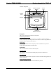
Crestron TPMC-10-DSW Docking Assembly for TPMC-10 Front View Components Enter Button Numeric Keypad Buttons Green LED Locking Arms Magnets Cradle and Interface Connector Controls The only user controls are located on the front panel. Numeric Keypad Buttons Five backlighted buttons, labeled 1-2, 3-4, 5-6, 7-8, and 9-0, are used to input a numeric code to open the docking station. These buttons can also be programmed via SIMPL Windows to perform other functions.
Docking Assembly for TPMC-10 Crestron TPMC-10-DSW Industry Compliance As of the date of manufacture, the units have been tested and found to comply with specifications for CE marking and standards per EMC and Radiocommunications Compliance Labelling. NOTE: This device complies with part 15 of the FCC rules.
Crestron TPMC-10-DSW Docking Assembly for TPMC-10 NOTE: When daisy-chaining Cresnet units, strip the ends of the wires carefully to avoid nicking the conductors. Twist together the ends of the wires that share a pin on the network connector, and tin the twisted connection. Apply solder only to the ends of the twisted wires. Avoid tinning too far up the wires or the end becomes brittle. Insert the tinned connection into the Cresnet connector and tighten the retaining screw.
Docking Assembly for TPMC-10 Crestron TPMC-10-DSW Installation To install the TPMC-10-DSW, complete the following procedure in the order provided. Tools required are a #2 Phillips screwdriver and a 9/64-inch Allen wrench. NOTE: The TPMC-1-DSW is designed for mounting in a vertical configuration only. Do not mount in a lectern or desktop configuration. 1. Prepare a cutout in the wall, centered between two studs, located on 16-inch centers. The hole should be 13 inches wide, and 11 inches high.
Crestron TPMC-10-DSW Docking Assembly for TPMC-10 4. With Cresnet power off, feed the Cresnet cable through the grommet in the bottom of the unit, and then through the captive tie-wrap on the rear plate of the unit. Attach the supplied terminal block connector to the Cresnet cable and plug into the port on the PC board. Make sure the cable is not pulling on the PC board connector, and tighten the tie-wrap. (Refer to the following illustration.
Docking Assembly for TPMC-10 Crestron TPMC-10-DSW 7. Secure the bezel into position using the four supplied 6-32x1/4” black pan-head screws B using a #2 Phillips screwdriver. 8. Hold the cover plate in position and use an Allen wrench to adjust the plate alignment screw shown in the previous illustration so the plate is flush with the adjacent surface of the bezel. (Turn clockwise to move it in; counterclockwise to move it out.) 9.
Crestron TPMC-10-DSW Docking Assembly for TPMC-10 • Crestron Database version 17.3.3 or later. • Crestron Toolbox version 1.01.06 or later • (Optional) Crestron SystemBuilder version 2.0.6 or later. Requires SIMPL Windows and Crestron Database 17.3.3. Programming with the Crestron SystemBuilder The easiest method of programming, but does not offer as much flexibility as SIMPL Windows.
Docking Assembly for TPMC-10 Crestron TPMC-10-DSW Expanded MC2E System Tree C2Net-Device Slot in Configuration Manager In Configuration Manager, drag the TPMC-10-DSW from the Cresnet I/O Control & Other Modules subfolder of the Touchpanels folder in the Device Library and drop it on the Cresnet Units symbol in System Views. The MC2E system tree displays the TPMC-10-DSW in C2Net-Device, Slot 1, with a default Net ID of 22, as shown in the following graphic.
Crestron TPMC-10-DSW Docking Assembly for TPMC-10 C2ENET-1-Device Slot in Configuration Manager To incorporate a TPMC-10 into the system, the control system requires either a plugin Ethernet card, or a built-in Ethernet port. The MC2E control system has a built-in Ethernet port in Slot 5 that can accept the TPMC-10 two-way wireless Ethernet touchpanel. The slot allows Cresnet communication between the touchpanel and the control system.
Docking Assembly for TPMC-10 Crestron TPMC-10-DSW Operation Normal operation consists of docking the touchpanel (performed by hand) into the TPMC-10-DSW or undocking electronically via the control system or via the docking station keypad, and then removing by hand. Docking the TPMC-10 To dock the TPMC-10, refer to the procedure below. 1.
Crestron TPMC-10-DSW Docking Assembly for TPMC-10 3. Press the upper edge of touchpanel inward to dock the touchpanel. Note that the docking station is a pneumatically damped assembly. When the touchpanel is in position, the upper latching assembly rotates down to secure the touchpanel in place. Undocking the TPMC-10 During normal operation, the user can undock the touchpanel via the controls on the front panel. The unit is supplied with the default pass code 1 2 3 4.
Docking Assembly for TPMC-10 Crestron TPMC-10-DSW Problem Solving Troubleshooting The table below provides corrective action for possible trouble situations. If further assistance is required, please contact a Crestron customer service representative. TPMC-10-DSW Troubleshooting TROUBLE POSSIBLE CAUSE CORRECTIVE ACTION TPMC-10-DSW does not unlatch touchpanel. Incorrect numeric code was entered. Enter the correct numeric code. Cresnet power is not connected.
Crestron TPMC-10-DSW Docking Assembly for TPMC-10 Return and Warranty Policies Merchandise Returns / Repair Service 1. No merchandise may be returned for credit, exchange, or service without prior authorization from CRESTRON. To obtain warranty service for CRESTRON products, contact the factory and request an RMA (Return Merchandise Authorization) number. Enclose a note specifying the nature of the problem, name and phone number of contact person, RMA number, and return address. 2.
Crestron Electronics, Inc. 15 Volvo Drive Rockleigh, NJ 07647 Tel: 888.CRESTRON Fax: 201.767.7576 www.crestron.com Operations Guide - DOC. 6400 (2013787) 10.05 Specifications subject to change without notice.