
Installation guide

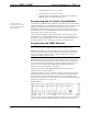
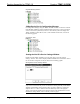
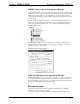
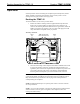


Table Of Contents
- Docking Assembly for TPMC-10: TPMC-10-DSW
- Six white LEDs
- One green LED
- Audio Transducer (Internal)

Docking Assembly for TPMC-10 Crestron TPMC-10-DSW
Operation
Normal operation consists of docking the touchpanel (performed by hand) into the
TPMC-10-DSW or undocking electronically via the control system or via the
docking station keypad, and then removing by hand.
Docking the TPMC-10
To dock the TPMC-10, refer to the procedure below.
1. Remove the adhesive backing from the supplied metal strips and attach
them to the rear of the TPMC-10, adjacent to the unit’s rubber feet, as
shown in the following illustration (dimensions are approximate). When the
TPMC-10 is docked, the magnets on the cover plate will engage the metal
strips and hold the touchpanel securely in position.
Metal Strip Attachment
Attach Metal Strips Here
TPMC-10 Rear View
0.25 in
(0.64 cm)
0.63 in
(1.6 cm)
0.25 in
(0.64 cm)
0.63 in
(1.6 cm)
Rubber
Foot
Rubber
Foot
2. Insert the bottom edge of the touchpanel into TPMC-10-DSW cradle so that
it engages the interface connector, and push the touchpanel back to rest
against the plate. Note that the magnets hold the touchpanel in position. The
green LED in the upper right corner of the docking station illuminates
indicating that the touchpanel is present and mated with the connector.
CAUTION: To avoid damage to the touchpanel or the docking station, make
certain that the TPMC-10 PCMCIA slot eject button and/or any PCMCIA card are
fully inserted and do not protrude above the top edge of the touchpanel before
actually docking the touchpanel.
NOTE: If additional metal strips are required, please contact a Crestron customer
service representative.
NOTE: As soon as the touchpanel is placed in the docking station cradle and mates
with the interface connector, power is supplied to the touchpanel, which also
recharges its built-in battery.
12 • Docking Assembly for TPMC-10: TPMC-10-DSW Operations and Installation Guide - DOC. 6400