
Specifications


Crestron Isys i/O
™
TPMC-15/17-L Series Touchpanel Media Centers
#
CONNECTORS
1
,
CONTROLS &
INDICATORS
DESCRIPTION
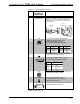
RS-232
(Continued)
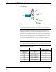
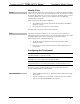
In the event that modular cables or an RJ-11 to DB9F
adapter is not available, the following diagram provides
information so that the cable can be fabricated on site.
(Alternatively, Crestron cable number STCP-502PC is
sold separately.)
1
2
3
4
5
6
7
8
9
1
3
6
5
4
2
2
3
5
7
8
1
CTS
GND
RXD
TXD
RTS
n/c
TO PC
COM PORT
TO RS-232
PORT
Part #
748047-1
Part #
641337
Part #
AWC10152-A
2
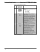
LAN
GREEN
LED
YELLOW
LED
PIN
1
PIN
8
(1) 8-wire RJ-45 with two LED indicators;
10BaseT/100BaseTX Ethernet port;
Green LED indicates link status;
Yellow LED indicates Ethernet activity.
PIN SIGNAL PIN SIGNAL
1 TX + 5 N/C
2 TX - 6 RC -
3 RC+ 7 N/C
4 N/C 8 N/C
3
G
(1) 6-32 screw, chassis ground lug.
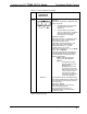
4
USB
2
Pins 1 2 3 4
(2) USB Type A female, USB 1.1 ports for
mouse, keyboard and storage devices.
3
PIN DESCRIPTION
1 +5 VDC
2 Data -
3 Data +
4 Ground
5
PWR
(1) 4-pin DC power jack, 12.5V DC power input
(external power supply included).
6
HEADPHONES
(1) 3.5 mm TRS mini phone jack;
Output power: 105 mW per channel;
Minimum impedance: 8 Ω.
7
PC CARD A - B
(2) Type II PC Card slots for memory expansion,
project upload and wireless NIC.
(Continued on following page)
Operations Guide – DOC. 6354B Touchpanel Media Centers: Crestron Isys i/O™ TPMC-15/17-L Series • 17
Connectors, Controls & Indicators (Continued)