Crestron TPS-4500IMPC Interface Module Operations Guide
This document was prepared and written by the Technical Documentation department at: Crestron Electronics, Inc. 15 Volvo Drive Rockleigh, NJ 07647 1-888-CRESTRON All brand names, product names and trademarks are the property of their respective owners. ©2003 Crestron Electronics, Inc.
Crestron TPS-4500IMPC Interface Module Contents Interface Module: TPS-4500IMPC 1 Introduction......................................................................................1 Features & Functions.............................................................1 Specifications.........................................................................1 Physical Description ..............................................................2 Industry Compliance...................................................
Crestron TPS-4500IMPC Interface Module Interface Module: TPS-4500IMPC Introduction Features & Functions The TPS-4500IMPC is an interface module designed for, and included with the Crestron TPS-4500 and TPS-4500V tilt touchpanels. The sleek design of the touchpanel base left little room for all the connectors that define the touchpanel's versatility.
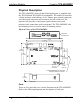
Interface Module Crestron TPS-4500IMPC Physical Description The TPS-4500IMPC, shown in the following diagram, is supplied with the TPS-4500 and TPS-4500V tilt touchpanels. The module is housed in a black enclosure with labeling. An AC adapter port, network connector, and video input connectors are located on one side of the unit. The opposite side provides a video input signal selector switch, and network/video connections to the touchpanel.
Crestron TPS-4500IMPC Interface Module NTSC/PAL VIDEO The NTSC/PAL video input consists of three connectors; two BNC connectors for unbalanced video signals and one 6-pin mini-connector for twisted pair wiring of balanced video signals. The video signal is connected to these ports and requires a TPS-4500V or installation of the TPS-VID-1 or TPS-VID-2 video card in a TPS-4500 touchpanel to display video. Consult the latest revision of the TPS-4500V & 4500LV Operations Guide (Doc.
Interface Module Crestron TPS-4500IMPC CAUTION: If power is provided to the TPS-4500IMPC from the +24VDC on a Cresnet connector or the PW-2420RU, power must not be applied to the power input on the touchpanel base. NOTE: When power is supplied through this connector, Crestron recommends disconnecting the +24 VDC on the Cresnet connector (if it is connected). NOTE: Use care in wiring installations to avoid applying 24 VDC power to Cresnet wiring from multiple sources.
Crestron TPS-4500IMPC Interface Module CAUTION: The 10-pin RJ-45 net/video connector cable supplied by Crestron is a custom cable and is the only one that should be used. The end of the cable has a metal shield that is required to protect the equipment. Using non-Crestron cables will result in damage to the product. BAL/COAX While not a port, these DIP switches are used to select which video connections (balanced or unbalanced) to use when receiving video signals.
Interface Module Crestron TPS-4500IMPC CAUTION: Possible equipment damage if miswired. NOTE: When installing network wiring, refer to the latest revision of the wiring diagram(s) appropriate to your specific system configuration, available from the Downloads | Product Manuals | Wiring Diagrams section of the Crestron website (www.crestron.com). NOTE: Do not power up system until all wiring is verified. Care should be taken to ensure data (Y, Z) and power (24, G) connections are not crossed.
Crestron TPS-4500IMPC Interface Module Wire Gauge Values RESISTANCE (R) WIRE GAUGE 4 16 6 18 10 20 15 22 13 Doubled CAT5 8.7 Tripled CAT5 NOTE: When daisy-chaining Cresnet units, strip the ends of the wires carefully to avoid nicking the conductors. Twist together the ends of the wires that share a pin on the network connector, and tin the twisted connection. Apply solder only to the ends of the twisted wires. Avoid tinning too far up the wires or the end becomes brittle.
Interface Module Crestron TPS-4500IMPC Hardware Hookup for the TPS-4500IMPC CONNECT TO 10-POSITION NET/VIDEO PORT ON TOUCHPANEL BALANCED "Y" FOR S-VIDEO OR COMPOSITE VIDEO BALANCED "C" FOR S-VIDEO OR COMPOSITE 2 FOR COMPOSITE VIDEO (TPS-VID-2 ONLY) UNBALANCED "C" FOR S-VIDEO OR COMPOSITE 2 FOR COMPOSITE VIDEO (TPS-VID-2 ONLY) UNBALANCED "Y" FOR S-VIDEO OR COMPOSITE VIDEO CONNECT TO CONTROL SYSTEM OR CRESNET PERIPHERALS SELECT BALANCED (TWISTED PAIR) OR COAX (UNBALANCED) FOR EACH VIDEO SIGNAL CONNECT O
Crestron TPS-4500IMPC Interface Module TPS-4500IMPC Troubleshooting (continued) TROUBLE POSSIBLE CAUSE(S) CORRECTIVE ACTION Touchpanel does not function. Touchpanel is not receiving power. Confirm that power is supplied via the power pack or the Cresnet connector (not both). Use Viewport (via SIMPL Windows or VT Pro-e) to poll the network. Verify network connection to the touchpanel. Verify proper connections on the touchpanel and TPS-4500IMPC.
Interface Module Crestron TPS-4500IMPC TPS-4500IMPC Troubleshooting (continued) TROUBLE POSSIBLE CAUSE(S) CORRECTIVE ACTION Video colors are wrong and/or moving. Touchpanel is set to auto-detect or S-video when two composite signals are plugged into the TPS-4500IMPC. Switch to “composite” video.
Crestron TPS-4500IMPC Interface Module Return and Warranty Policies Merchandise Returns / Repair Service 1. No merchandise may be returned for credit, exchange, or service without prior authorization from CRESTRON. To obtain warranty service for CRESTRON products, contact the factory and request an RMA (Return Merchandise Authorization) number. Enclose a note specifying the nature of the problem, name and phone number of contact person, RMA number, and return address. 2.
Crestron Electronics, Inc. 15 Volvo Drive Rockleigh, NJ 07647 Tel: 888.CRESTRON Fax: 201.767.7576 www.crestron.com Operations Guide - DOC. 6163 08.03 Specifications subject to change without notice.