
Specifications

Crestron Isys™ TPS-5000L 12 Inch Lectern/Wall Mounted Touchpanel
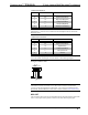
AUDIO Pinouts-Balanced
PIN # DESIGNATION DESCRIPTION
1 S Shield (no connection)
2 R+ Right Input (Positive)
3 R- Right Input (Negative)
4 L+ Left Input (Positive)
5 L- Left Input (Negative)
6 S Shield (no connection)
NOTE: When sending balanced audio from a CNX-BIPAD8, only the Positive (+)
and Negative (-) wires are to be connected to the touchpanel. Do not connect the
Shield (S) wires.
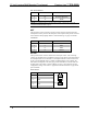
AUDIO Pinouts-Unbalanced
PIN # DESIGNATION DESCRIPTION
1 S Ground
2 R+ Right Input (Positive)
3 R- Right Ground
4 L+ Left Input (Positive)
5 L- Left Input Ground
6 S Ground
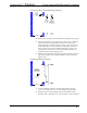
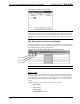
NOTE: Using two jumpers, connect R Shield to R – and L Shield to L – respectively
at the TPS-5000L Audio Input connector. Refer to the following diagram.
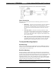
Wiring for Unbalanced Audio
S
+
Jumpers
+
R
-
R
+
L
-
LS
+
NOTE: The TPS-5000L can receive audio signals over CAT5 wiring. For additional
information on audio connections over CAT5, refer to the latest version of the
Crestron CAT5 Wiring Reference Guide (Doc. 6137) which is available from the
Downloads | Product Manuals section of the Crestron website (www.crestron.com
).
MIC OUT
This 3-position mini-connector provides balanced line level microphone output with
AGC. A description of the pinouts is shown in the table after this paragraph.
Operations Guide - DOC. 5783A 12 Inch Lectern/Wall Mount Touchpanel: Crestron Isys™ TPS-5000L • 17