Crestron TPS-MEM64MB & TPS-MEM128MB Flash Memory for TPS User Interfaces Installation Guide
This document was prepared and written by the Technical Documentation department at: Crestron Electronics, Inc. 15 Volvo Drive Rockleigh, NJ 07647 1-888-CRESTRON All brand names, product names and trademarks are the property of their respective owners. ©2004 Crestron Electronics, Inc.
Crestron TPS-MEM64MB & TPS-MEM128MB Flash Memory Contents Flash Memory for TPS User Interfaces: TPS-MEM64MB & TPS-MEM128MB 1 Introduction........................................................................................................1 Features and Functions ..........................................................................1 Physical Description ..............................................................................2 Industry Compliance..............................................
Crestron TPS-MEM64MB & TPS-MEM128MB Flash Memory Flash Memory for TPS User Interfaces: TPS-MEM64MB & TPS-MEM128MB Introduction Features and Functions There are two flash memory expansion modules available for select TPS products: TPS-MEM64MB and TPS-MEM128MB. These memory modules directly replace the original 16MB memory module that is supplied with the TPS device.
Flash Memory Crestron TPS-MEM64MB & TPS-MEM128MB Physical Description Each memory expansion module is a printed circuit board (PCB) designed for installation into a specific memory socket on the TPS device’s motherboard. Industry Compliance As of the date of manufacture, the flash memory for TPS user interfaces has been tested and found to comply with specifications for CE marking and standards per EMC and Radiocommunications Compliance Labelling.
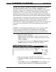
Crestron TPS-MEM64MB & TPS-MEM128MB Flash Memory NOTE: The Crestron Viewport is available as a pull-down command from SIMPL Windows and VT Pro-e (Tools | Viewport) or as a standalone utility. The Viewport utility performs multiple system tasks, primarily via an RS-232 or TCP/IP connection between the control system and a PC.
Flash Memory Crestron TPS-MEM64MB & TPS-MEM128MB Search for the item titled “Flash Total Size”. The amount of flash memory that is installed in the device is shown. Memory Module Expansion Compatibility Only select models of the TPS-4500, TPS-5000, TPS-6000, and TPS-TPI series of TPS devices are compatible with the TPS-MEM64MB and TPS-MEM128MB flash memory expansion modules. Refer to the following table for a list of fully compatible models.
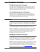
Crestron TPS-MEM64MB & TPS-MEM128MB Flash Memory Tilt Model Inspection Procedure Only TPS touchpanels with a jumper for selecting memory voltage are compatible with the TPS-MEM64MB and the TPS-MEM128MB. To confirm the presence of the jumper, perform steps 1 through 10 of the “Tilt Model Installation Procedure” on page 5. Lectern Model Inspection Procedure Only TPS devices with a jumper for selecting memory voltage are compatible with the TPS-MEM64MB and the TPS-MEM128MB.
Flash Memory Crestron TPS-MEM64MB & TPS-MEM128MB NOTE: The diagrams in this procedure show a TPS-5000 touchpanel, but the steps for all other TPS touchpanels are identical. 1. If an optional external power pack is utilized, disconnect the power pack from the touchpanel rear port labeled 24VDC 2A. 2. To prevent errors when re-connecting, label and disconnect all cables attached to the touchpanel’s rear panel ports. 3.
Crestron TPS-MEM64MB & TPS-MEM128MB Flash Memory Remove Touchpanel Base Cover 9. If installed, remove the TPS-VID-1 or TPS-VID-2 video expansion card to obtain unobstructed access to the memory socket, as shown in the following diagram. If there is no video expansion card, continue with the next step. TPS-VID-1 / TPS-VID-2 Removal Installation Guide - DOC.
Flash Memory Crestron TPS-MEM64MB & TPS-MEM128MB 10. As shown in the following diagram, locate the jumper for selecting the memory module voltage. If the jumper is not present on the touchpanel motherboard, the TPS-MEM64MB and TPS-MEM128MB cannot be installed. If the jumper is present, continue to the next step. Jumper Location LOCATION OF JUMPER FOR SELECTING VOLTAGE FOR TPS-MEM-64MB AND TPS-MEM128MB, MOVE JUMPER TO 3.
Crestron TPS-MEM64MB & TPS-MEM128MB Flash Memory 11. Move the jumper to the 3.3V position by placing the jumper over the center pin and the pin labeled 3.3V as shown in the following diagram. Jumper in 3.3V Position NOTE: The memory expansion module will not work if the jumper is in the “+5V” position. 12. As shown in the following diagram, locate the memory socket.
Flash Memory Crestron TPS-MEM64MB & TPS-MEM128MB 15. Observe polarity (as shown in the previous illustration) and insert the new memory module into the socket at a slight angle. 16. Apply even pressure to the module and level it off, parallel to the motherboard. The two metallic side clips snap into place as it becomes seated. 17. If removed, return the TPS-VID-1 or TPS-VID-2 expansion card. 18. Position the touchpanel base cover onto the base. 19.
Crestron TPS-MEM64MB & TPS-MEM128MB Flash Memory applicable, the back box Installation Guide. Disconnect power and perform the installation procedure in reverse to remove the user interface. The latest versions of the Operations & Installation Guides are available from the Downloads | Product Manuals section of the Crestron website (www.crestron.com). 1. To prevent scratching of the screen (TPS-TPI excluded), place the touchpanel facedown onto a padded surface. 2.
Flash Memory Crestron TPS-MEM64MB & TPS-MEM128MB Remove Rear Cover 4. To obtain unobstructed access to the memory socket, remove the expansion cover plate or if previously installed, the TPS-VIDL-1 or TPS-VIDL-2 video expansion card. Each procedure is defined in the following sub-steps. 4a. If the expansion cover plate is present, refer to the following diagram. Using a #1 Phillips screwdriver, loosen and remove the two screws that secure the expansion cover plate and remove the plate.
Crestron TPS-MEM64MB & TPS-MEM128MB Flash Memory Remove Expansion Cover Plate 4b. If a TPS-VIDL-1 or TPS-VIDL-2 video expansion card is present, refer to the following diagram. Completely loosen the knurled mounting screws and carefully remove the expansion card from the device’s motherboard connector without bending any of the pins on the device’s interface connector. TPS-VIDL-1/TPS-VIDL-2 Removal Installation Guide - DOC.
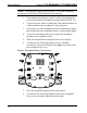
Flash Memory Crestron TPS-MEM64MB & TPS-MEM128MB 5. As shown in the following diagram, locate the jumper for selecting memory module voltage. If the jumper is not present on the device’s motherboard, the TPS-MEM64MB and TPSMEM128MB cannot be installed. If the jumper is present, continue to the next step. Jumper Location FOR TPS-MEM-64MB AND TPS-MEM128MB, MOVE JUMPER TO 3.3V POSITION LOCATION OF JUMPER FOR SELECTING VOLTAGE CRESTRON ELECTRONICS INC.
Crestron TPS-MEM64MB & TPS-MEM128MB Flash Memory Jumper in 3.3V Position NOTE: The memory expansion module will not work if the jumper is in the “+5V” position. 7. As shown in the following diagram, locate the memory socket. Memory Socket Location SIDE CLIP (ONE AT EACH END) CRESTRON ELECTRONICS INC. ROCKLEIGH, NJ 07647 USA LOCATION OF MEMORY SOCKET WITH MEMORY MODULE + S S R+ RL+ LS AUDIO INPUT MIC OUT NET 24 Y Z G RS-232 NOTE POLARITY OF MEMORY MODULE (NOTCH IN CORNER OF BOARD) 8.
Flash Memory Crestron TPS-MEM64MB & TPS-MEM128MB 12. Return the expansion cover plate or TPS-VIDL expansion card. CAUTION: If the expansion card is present, the TPS-VIDL connectors may have to be aligned slightly to fit through the openings in the rear cover. Align the connectors of this card (or any other optional card that is installed) carefully to prevent damage to the card, cover, or touchpanel. 13. Install the rear cover by sliding it over any expansion card connectors that may be present. 14.
Crestron TPS-MEM64MB & TPS-MEM128MB Flash Memory Problem Solving Troubleshooting The following table provides corrective action for possible trouble situations. If further assistance is required, please contact a Crestron customer service representative. TPS-MEM64MB & TPS-128MB Troubleshooting TROUBLE POSSIBLE CAUSE(S) CORRECTIVE ACTION Touchpanel does not operate after replacement. Improper connection; module improperly installed. Module installed with reverse polarity.
Flash Memory Crestron TPS-MEM64MB & TPS-MEM128MB Further Inquiries If you cannot locate specific information or have questions after reviewing this guide, please take advantage of Crestron's award winning customer service team by calling the Crestron corporate headquarters at 1-888-CRESTRON [1-888-273-7876]. For assistance in your local time zone, refer to the Crestron website (www.crestron.com) for a listing of Crestron worldwide offices.
Crestron TPS-MEM64MB & TPS-MEM128MB Flash Memory Return and Warranty Policies Merchandise Returns / Repair Service 1. No merchandise may be returned for credit, exchange, or service without prior authorization from CRESTRON. To obtain warranty service for CRESTRON products, contact the factory and request an RMA (Return Merchandise Authorization) number. Enclose a note specifying the nature of the problem, name and phone number of contact person, RMA number, and return address. 2.
Crestron Electronics, Inc. 15 Volvo Drive Rockleigh, NJ 07647 Tel: 888.CRESTRON Fax: 201.767.7576 www.crestron.com Operations Guide - DOC. 6261 04.04 Specifications subject to change without notice.