
User Guide


Crestron Isys™ TPS-TPI Touchpanel Interface
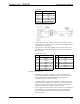
RS-232 Pinouts
PIN DESCRIPTION
1CTS
2GND
3RXD
4TXD
5RTS
6 No Connect (N/C)
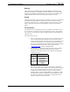
PC to TPS-TPI Cable Specifications
• AUDIO OUTPUT – This standard mini phone jack (12mW, 32 ohms
load) provides line level stereo audio output to an external audio system
or headphone set, not supplied.
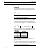
• VGA OUTPUT – This DB15 female connector outputs XGA (1024 x
768) RGB video. Description of the pinouts is shown in the table after
this paragraph.
VGA OUTPUT Pinouts
PIN DESCRIPTION PIN DESCRIPTION
1RED 9 NC
2 GREEN 10 GND
3BLUE 11 NC
4NC 12NC
5 GND 13 HSYNC/COMPOSITE SYNC
6 GND 14 VSYNC
7 GND 15 NC
8GND
NC = Not Connected
The optional connectors are:
• RGB INPUT – These five connectors are made available with the
purchase and installation of the TPS-XVGAL, a scan converter card.
Consult the latest revision of the TPS-XVGAL Operations &
Installation Guide (Doc. 5828) for details.
• NTSC/PAL INPUT – These three connectors are made available with
the purchase and installation of the TPS-VIDL, composite and S-video
input for TV video card. Consult the latest revision of the TPS-VIDL
Operations & Installation Guide (Doc. 5830) for details.
• LAN – This port is made available with the purchase and installation of
the TPS-ENETL, a 10/100 BaseT Ethernet card. Consult the latest
revision of the TPS-ENETL Operations & Installation Guide (Doc.
5829) for details.
Operations Guide - DOC. 5855 Touchpanel Interface: Crestron Isys™ TPS-TPI • 3