This document was prepared and written by the Technical Documentation department at: Crestron Electronics, Inc.
Crestron TPS-XTXRF Two-Way RF Transceiver Module Contents Two-Way RF Transceiver Module: TPS-XTXRF 1 Description................................................................................................................................. 1 Functional Description ................................................................................................ 1 Physical Description....................................................................................................
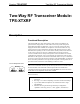
Crestron TPS-XTXRF Two-Way RF Transceiver Module Two-Way RF Transceiver Module: TPS-XTXRF Description Functional Description The TPS-XTXRF Two-Way radio frequency (RF) Transceiver Module is an optional feature designed for use with certain Crestron Isys™ tilt touchpanels (TPS-5000, TPS-6000, and TPS-4500 – refer to note on this page for this unit).
Crestron TPS-XTXRF Two-Way RF Transceiver Module Included with the TPS-XTXRF are a Crestron TPS-XBTP Battery Pack and a TPS-XDS Docking Station. The TPS-XDS provides operating power for the docked RF-enabled touchpanel and charges the TPS-XBTP when the battery pack is installed in the touchpanel. An external power pack PW-2420RU is also supplied to power the docking station/touchpanel and simultaneously charge the TPS-XBTP.
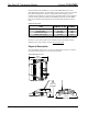
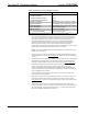
Crestron TPS-XTXRF Two-Way RF Transceiver Module TPS-XTXRF Installed on Touchpanel (Side View) Leading Specifications The table below and continued on the next two pages provides a summary of leading specifications for the TPS-XTXRF. Leading Specifications of the TPS- XTXRF SPECIFICATION DETAILS Compatible Touchpanels Use with TPS-4500 (except ZA11323), TPS-5000, and TPS-6000 Power Requirements RF Transmitting Power Communications TPS-XBTP battery pack1 100 mW Bidirectional Spread Spectrum 2.
Two-Way RF Transceiver Module Crestron TPS-XTXRF Leading Specifications of the TPS- XTXRF (continued) SPECIFICATION DETAILS Operating Ranges (line of sight) Minimum Distance Maximum Distance Indoor Maximum Distance Outdoor Operating Temperature Charging Temperature Storage Temperature SIMPL™ Windows® Crestron Database IsysTM Touchpanel Firmware 2-Series Control System Update File 6 2 3 ft 2 150 ft 2 1000 ft Approximately +32o to +104oF (0o to 40oC) Approximately +50o to +95oF (10o to 35oC) Approximate
Crestron TPS-XTXRF Two-Way RF Transceiver Module Leading Specifications of the TPS- XTXRF (continued) SPECIFICATION DETAILS CNMSX-AV/Pro Update File CNRACKX/-DP Update File CEN/CN-TVAV Update File ST-CP Update File Weight of TPS-XTXRF (no touchpanel) Version 51020X.UPZ or later 8 & 9 Version 51020W.UPZ or later 8 & 9 Version 51205V.UPZ or later 8 & 9 Version 40104S.UPZ or later 9 & 10 Weight: 15.40 oz (0.44 kg) 11 9 CNX update files are required for either CNMSX-AV/Pro or CNRACKX/-DP.
Two-Way RF Transceiver Module Crestron TPS-XTXRF Installation The only tools required for installation of the TPS-XTXRF onto an Isys™ tilt touchpanel are a #1 Phillips screwdriver and a grounding strap (or grounded workstation). CAUTION: The TPS-XTXRF and the touchpanel contain ESD sensitive devices. Perform the following procedure while wearing a grounding strap that is properly grounded or on a grounded work station to avoid damaging the card and/or the touchpanel.
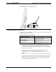
Crestron TPS-XTXRF Two-Way RF Transceiver Module Installation Diagram 1 of 12 - Remove Touchpanel Base Cover Screws CLEAN PANEL WITH SOFT CLOTH ONLY ELECTRONICS, INC Rockleigh, NJ 07647 U.S.A. READ INSTRUCTION MANUAL BEFORE OPERATING NO USER SERVICABLE PARTS UNDER THIS COVER ELECTRONICS, INC Rockleigh, NJ 07647 U.S.A. FCC ID: EROTPS-6000 SEE MANUAL USE POWER PACK PW-2420RU TPS-6000 ZA***** C000000 7. Place the touchpanel upright on the work surface. 8.
Two-Way RF Transceiver Module Crestron TPS-XTXRF NOTE: If the TPS touchpanel is equipped with an optional TPS-XVGA or TPS-XVGA-BV expansion card, the fan assembly on the card must be removed because it interferes with the placement of the TPS-XTXRF. Removal will not introduce cooling problems because the TPS-XTXRF has fans for adequate air circulation. Therefore, there is no need to re-install the fan. Continue to the next step.
Crestron TPS-XTXRF Two-Way RF Transceiver Module Installation Diagram 4 of 12 - Remove Mounting Screws & Fan Assembly NOTE: If the TPS touchpanel is equipped with an optional TPS-XVGA or TPS-XVGA-BV expansion card, temporarily removing the card makes installation of the TPS-XTXRF cable connectors easier. However, re-installation of the card requires a #1 Phillips screwdriver (1.5” length). 11. Refer to the diagram below. Position the TPS-XTXRF onto the touchpanel as shown.
Two-Way RF Transceiver Module Crestron TPS-XTXRF 12. Refer to the diagram below. Making sure that the RED wire at one end of the large TPS-XTXRF connector faces in toward the center of the unit, attach the TPS-XTXRF large connector to P11 (connector on the touchpanel) so that all pins mate. CAUTION: The touchpanel can be damaged when power is applied, if the large TPS-XTXRF connector is mated incorrectly (any pin is exposed). Installation Diagram 6 of 12 - Attach Large TPS-XTXRF Connector RED WIRE 13.
Crestron TPS-XTXRF Two-Way RF Transceiver Module Installation Diagram 8 of 12 - TPS-XTXRF Ribbon Cable Connector Detail RED STRIPE KEY SLOT Installation Diagram 9 of 12 - Attach TPS-XTXRF Ribbon Cable Connector NOTE: If an optional TPS-XVGA or TPS-XVGA-BV expansion card was temporarily removed to make installation of the TPS-XTXRF cable connectors easier, re-install the card. Tighten the card mounting screws to finger-tight then using a #1 Phillips screwdriver (1.
Crestron TPS-XTXRF Two-Way RF Transceiver Module Installation Diagram 10 of 12 - Lower TPS-XTXRF onto Touchpanel Base 16. Hold the TPS-XTXRF in place and position the touchpanel face-down onto a padded surface to prevent scratching of the screen. 17. Refer to the diagram below. Re-install the eight base cover screws to finger-tight then, using a #1 Phillips screwdriver, tighten an additional 1/8-turn.
Crestron TPS-XTXRF Two-Way RF Transceiver Module 19. Refer to the diagram below. By hand, thread the antenna onto the antenna mounting post to finger-tight. Installation Diagram 12 of 12 - Install Antenna 20. Apply power to the touchpanel. There are four ways to operate the TPS-XTXRF equipped touchpanel. First, a charged TPS-XBTP Battery Pack can be installed into the touchpanel directly.
Crestron TPS-XTXRF Two-Way RF Transceiver Module Setup Programming with SIMPL Windows SIMPL (Symbol Intensive Master Programming Language) is an easy-to-use programming language that is completely integrated and compatible with all Crestron system hardware. The objects that are used in SIMPL are called symbols. SIMPL Windows offers drag and drop functionality in a familiar Windows® environment. SIMPL Windows is Crestron's software for programming Crestron control systems.
Crestron TPS-XTXRF Two-Way RF Transceiver Module NOTE: Commenting out the Cresnet ID of the RF receiver in the SIMPL Windows program will allow only Cresnet (wired touchpanel) use of the TPS-XTXRF equipped touchpanel. To configure a TPS-RFGWX Two-Way RF Transceiver (sold separately), refer to the latest revision of the TPS-RFGWX Operations & Installation Guide (Doc. 5847). This document can be obtained from the Downloads | Product Manuals section of the Crestron website (www.crestron.com).
Two-Way RF Transceiver Module Crestron TPS-XTXRF RF Configuration Crestron IsysTM tilt touchpanel are default configured for Cresnet (wired) operation. To configure the TPS-XTXRF equipped touchpanel for RF communication, it is necessary to access a series of setup screens on the touchpanel. NOTE: For additional touchpanel configuration information, consult the appropriate IsysTM tilt touchpanel operations guide.
Crestron TPS-XTXRF Two-Way RF Transceiver Module ID DOWN or UP button to select the RF ID that was assigned to the touchpanel in “Programming with SIMPL Windows”. 7. The RF CHANNEL is important because it allows the radio in a touchpanel to communicate with the radio in the TPS-RFGWX. If the RF CHANNELs match, the RF-enabled panel can communicate to the system via the pre-defined frequency channel.
Crestron TPS-XTXRF Two-Way RF Transceiver Module NOTE: Once configured for Cresnet and RF operation, the function of the touchpanel is determined by the attachment of the NET/VIDEO cable to the touchpanel. To use the touchpanel as a Cresnet wired unit, connect the NET/VIDEO cable to the NET/VIDEO port of the touchpanel. To use the touchpanel as an RF unit, disconnect the cable from the touchpanel. NOTE: Touchpanel wake-up from standby mode may take 2-5 seconds.
Crestron TPS-XTXRF Two-Way RF Transceiver Module TPS-XTXRF Troubleshooting (continued) TROUBLE POSSIBLE CAUSE(S) CORRECTIVE ACTION TPS-XBTP battery Position the touchpanel onto the TPS-XDS docking station to charge the pack has low TPS-XBTP battery pack or to "hot swap" charge. battery pack. Touchpanel is in Verify that large amount of metal is not in vicinity of metal. vicinity of transmission. Touchpanel is too Position the touchpanel to within operating range.
Two-Way RF Transceiver Module Crestron TPS-XTXRF Software License Agreement This License Agreement (“Agreement”) is a legal contract between you (either an individual or a single business entity) and Crestron Electronics, Inc. (“Crestron”) for software referenced in this guide, which includes computer software and, as applicable, associated media, printed materials, and “online” or electronic documentation (the “Software”).
Crestron TPS-XTXRF Two-Way RF Transceiver Module If You are a business or organization, You agree that upon request from Crestron or its authorized agent, You will within thirty (30) days fully document and certify that use of any and all Software at the time of the request is in conformity with Your valid licenses from Crestron of its authorized agent.
Crestron TPS-XTXRF Two-Way RF Transceiver Module Return and Warranty Policies Merchandise Returns / Repair Service 1. No merchandise may be returned for credit, exchange, or service without prior authorization from CRESTRON. To obtain warranty service for CRESTRON products, contact the factory and request an RMA (Return Merchandise Authorization) number. Enclose a note specifying the nature of the problem, name and phone number of contact person, RMA number, and return address. 2.
Crestron TPS-XTXRF Two-Way RF Transceiver Module This page intentionally left blank. Operations & Installation Guide - DOC.
Crestron Electronics, Inc. 15 Volvo Drive Rockleigh, NJ 07647 Tel: 888.CRESTRON Fax: 201.767.7576 www.crestron.com Operations & Installation Guide - DOC. 5844 03.02 Specifications subject to change without notice.