
System information

Door
Motors
o
=
=
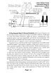
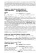
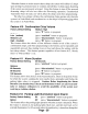
3 Wire Positive Pulse
Ooorlocks Using
An
Optional
OLS
&2 SPOT
Relays
Vehicle's Doorlock
Relay Control Unit
DLS Blue wire to
Switch "unlock" wire.
DLS
Relay
DLS Red connector
plugs into the control
module's Red port.
JTr~~~
'---
..
--+------i
Unlock
....
-+-----
...
------t
Lock
DLS Green wire to
Switch "lock" wire.
Doorlock Switch
DLS Violet Wire
to
Constant +
(+)12 Volts.
DLS Brown
& White wires
are not used in this system.
+12V
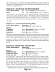
5 Wire Reversal Rest At Ground Systems differ from the Negative and
Positive Pulse systems as there are no relays
or
doorlock control unit. In this type
of
system, the switches themselves supply the positive voltage directly to the
doorlock actuators, and, more importantly, provide the return ground path. The
important thing to rememberis the wires
in
this system rest at ground, which means
that the wires must be "opened",
or
cut, to make the connections.
Examine the wires
on
the back
ofthe
switch. Normally five wires will be found-
one will be constant 12 volts positive, regardless
ofthe
switch's position; two wires
will be grounded regardless
of
the switch's position.
Of
the two remaining wires,
one will show
12
volts positive when the switch
is
pushed to "lock", and the other
will show 12 volts positive when the switch is pushed to "unlock".
The two later wires are both routed to the doorlock actuators and are connected
to either
end
of
the actuator's motor winding. When the switch is pushed to one
position, one
of
these two wires will have
12
volts. This voltage flows through the
wire to the actuator's motor winding, and since the other wire is still resting
at
ground an electrical circuit is completed. When the switch is pushed to the opposite
position the electrical flow is reversed.
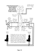
Oncedetermined, the correctwires mustbe cut. Notice in the following diagram
that the driver's switch is the primary switch and referred to as the "switch" wires.
The wires that go to the secondary switch are referred to as the "motor" wires. Even
though the cut is made between the switches, the two sides are still correctly called
the "switch" and the "motor" sides, with consideration
of
"Primary" and "Second-
ary" switch.
Page -
21